Quantcast
Channel: Low Voltage - Technical Articles | EEP - Electrical Engineering Portal
Viewing all 182 articles
Browse latest View live

Electrical Safety Standards for LV/MV/HV (Part-2)

$
0
0
Electrical Safety Standards for LV/MV/HV part 2

Electrical Safety Standards for LV/MV/HV part 2 (on photo Downtown LA distribution power lines; photo by Hal Bergman Photography @Flickr)


Continued from part 1Electrical Safety Standards for LV/MV/HV (Part-1)

Content

Standard: Northern Ireland Electricity (NIE), 6/025 ENA

  1. Clearances of Electrical Line to Ground and Roads
  2. Clearances of Electrical Line to Other Objects
  3. Clearances of Electrical Line to Trees and Hedges
  4. Clearances of Electrical Line to Street Lighting
  5. Clearances of Electrical Line to Waterways
  6. Clearances to Railways
  7. Clearances of Electrical Line to Fuel Tanks
  8. Clearances of Electrical Lines to other Electrical Lines
  9. Vertical Passing Clearance (sites where vehicles will pass below the lines)
  10. Horizontal Clearance (sites where there will be no work or passage of plant under lines)
  11. Distance between Conductors of Same/Different Circuit (On Same Support)
  12. Vertical Distance between Conductors of different Circuit (On Different Support)
  13. Distance between Conductors (Taken down from Pole to other Support, on Transformer)
  14. Horizontal Distance of Telecommunication Line & Overhead Line
  15. Passage Way for Metal-Clad Switchgear
  16. Safe approach distance for Person from Exposed Live Parts

Standard: Northern Ireland Electricity (NIE), 6/025 ENA

Clearances of Electrical Line to Ground and Roads

Description of Clearance0.4 KV11 KV33KV110KV220 KV400KV
Line conductor to any point not over road5.2 Meter6.1 Meter6.4 Meter6.4 Meter7.0 Meter7.0 Meter
Line conductor to road surface5.8 Meter6.1 Meter6.4 Meter6.4 Meter7.4 Meter8.1 Meter
Line conductor to road surface of high load routes6.9 Meter6.9 Meter6.9 Meter7.2 Meter8.5 Meter9.2 Meter
Bare live metalwork ( transformer terminals, jumper connections, etc)4.6 Meter4.6 Meter4.6 Meter---

Go to Content ↑


Clearances of Electrical Line to Other Objects

Description of Clearance<11 KV33 KV110KV220KV400 KV
Line conductor or bare live metalwork to any object that is normally accessible (including permanently mounted ladders and access platforms) or to any surface of a building3.0 Meter3.0 Meter3.4 Meter4.6 Meter5.3 Meter
Line conductor or bare live metalwork to any object to which access is not required AND on which a person cannot stand or lean a ladder0.8 Meter0.8 Meter1.2 Meter2.4 Meter3.1 Meter
Line conductors to irrigates, slurry guns and high-pressure hoses30 Meter30 Meter30 Meter30 Meter30 Meter
Line conductors to playing fields8.5 Meter8.5 Meter8.5 Meter8.5 Meter8.5 Meter
Line conductors to Caravan Sites9.0 Meter9.0 Meter9.0 Meter9.0 Meter9.0 Meter
Horizontal clearances to wells15.0 Meter15.0 Meter15.0 Meter15.0 Meter15.0 Meter

Go to Content ↑


Clearances of Electrical Line to Trees and Hedges

Description of Clearance<11 KV33 KV110KV220KV400 KV
Line conductor or bare live metalwork to trees or hedges unable to support a ladder or being climbed.0.8 Meter0.8 Meter1.2 Meter2.4 Meter3.1 Meter
Line conductor or bare live metalwork to trees or hedges capable of supporting a ladder or being climbed.3.0 Meter3.0 Meter3.4 Meter4.6 Meter5.3 Meter
Line conductor or bare live metalwork to trees falling towards the overhead line with the line conductors hanging vertically.0.8 Meter0.8 Meter1.2 Meter2.4 Meter3.1 Meter
Line conductors to trees in Orchards3.0 Meter3.0 Meter3.4 Meter4.6 Meter5.3 Meter

Go to Content ↑


Clearances of Electrical Line to Street Lighting

Description of Clearance0.4 KV11 KV33KV110KV220 KV400KV
Line conductor to Lantern on same pole1.0 Meter-----
Bare line conductor to lantern or column below.1.5 Meter-----
Insulated line conductor to column0.3 Meter-----
Insulated line conductor to lantern1.0 Meter-----
Column to nearest LV pole1.5 Meter-----
Line conductor to street lighting column with
(1) Column in normal upright position.-1.7 Meter1.7 Meter2.3 Meter3.3 Meter4.0 Meter
(2) Column falling towards line with line conductor hanging vertically only-1.7 Meter1.7 Meter2.3 Meter3.3 Meter4.0 Meter
(3) Column falling towards line-0.4 Meter0.4 Meter0.8 Meter1.4 Meter1.9 Meter

Go to Content ↑


Clearances of Electrical Line to Waterways

Description of Clearance0.4 KV11 KV33KV110KV220 KV400KV
Navigable Waters: Lower bank to conductor or earth wire10.5 Meter10.5 Meter10.5 Meter10.5 Meter10.5 Meter10.5 Meter
Minor Watercourses : Lower bank to conductor or earth wire7.6 Meter7.6 Meter7.6 Meter7.6 Meter7.6 Meter7.6 Meter

Go to Content ↑


Clearances to Railways

Description of Clearance0.4 KV11 KV33KV110KV220 KV400KV
Line conductor to ground level6.1 Meter6.1 Meter6.1 Meter6.7 Meter7.0 Meter7.6 Meter
Line conductor to ground level on or across vehicle parks7.6 Meter8.5 Meter8.5 Meter9.1 Meter9.4 Meter10.1 Meter
Line conductor to ground level at roads and yards, where road mobile cranes are likely to be employed10.7 Meter10.7 Meter10.7 Meter11.2 Meter11.5 Meter12.2 Meter
Line conductor to Rail level7.3 Meter7.3 Meter7.3 Meter8.0 Meter8.2 Meter8.8 Meter
Line conductor to the level of buildings, gantries or other structures (including those carrying traction wires) on which a man may be3.0 Meter3.0 Meter3.0 Meter3.7 Meter4.6 Meter6.1 Meter
Line conductor to poles and other projections.2.4 Meter2.7 Meter2.7 Meter3.0 Meter3.7 Meter5.5 Meter
Line conductor to any other wire other than traction wires.1.8 Meter1.8 Meter1.8 Meter2.4 Meter3.0 Meter3.7 Meter

Go to Content ↑


Clearances of Electrical Line to Fuel Tanks>

Description of Clearance0.4 KV11 KV33KV110KV220 KV400KV
Horizontal clearance from line conductors to petrol tanks and vents15 Meter15 Meter15 Meter15 Meter15 Meter15 Meter
Horizontal clearance from line conductors to liquid gas tanks
(1) 459 to 2273 litre capacity3.0 Meter3.0 Meter3.0 Meter3.4 Meter4.6 Meter5.3 Meter
(2) 2274 to 9092 litre capacity7.6 Meter7.6 Meter7.6 Meter7.6 Meter7.6 Meter7.6 Meter
(3) More than 9093 litre.15 Meter15 Meter15 Meter15 Meter15 Meter15 Meter
Vertical clearance from line conductors to fuel oil tanks Please refer Clearances to Objects

Go to Content ↑


Clearances of Electrical Lines to other Electrical Lines

Description of Clearance0.4 KV11 KV33KV110KV220 KV400KV
Lowest line conductor or earth wire of upper line to highest line conductor of lower line.1.0 Meter1.8 Meter2.0 Meter2.5 Meter3.7 Meter4.4 Meter
Lowest line conductor or earth wire of upper line to earth wire of lower line where erected.0.7 Meter1.4 Meter1.6 Meter2.5 Meter3.7 Meter4.4 Meter
Lowest line conductor or earth wire of upper line to any point on a support of the lower line on which a person may stand.2.7 Meter2.8 Meter3.0 Meter3.4 Meter4.6 Meter5.3 Meter
Support of upper line and any conductor of lower line.7.5 Meter7.5 Meter7.5 Meter15 Meter15 Meter15 Meter

Go to Content ↑


Vertical Passing Clearance (sites where vehicles will pass below the lines)

Description of Clearance<33 KV110KV220KV400 KV
Passing clearance: fixed height loads0.8 Meter1.4 Meter2.4 Meter3.1 Meter
Passing Clearance: variable height loads.2.3 Meter3.2 Meter4.1 Meter5.0 Meter

Go to Content ↑


Horizontal Clearance (sites where there will be no work or passage of plant under lines)

Description of Clearance<33 KV110KV220KV400 KV
Minimum horizontal distances to safety barriers6.0 Meter9.0 Meter12.0 Meter14.0 Meter

Go to Content ↑


Distance between Conductors of Same/Different Circuit (On Same Support)

Higher Voltage of either CircuitLower Voltage of either CircuitDistance between Circuits
< 33 KV< 1 KV1.0 Meter
< 33 KV> 1 KV1.2 Meter
33 KV to 110 KV< 1 KV1.5 Meter
33 KV to 110 KV> 1 KV2.0 Meter
Above 110 KVAll2.5 Meter

Go to Content ↑


Vertical Distance between Conductors of different Circuit (On Different Support)

Higher Voltage of either CircuitDistance between Circuits
< 1 KV0.6 Meter
1 KV to 33 KV1.2 Meter
33 KV to 66 KV1.8 Meter
110 KV2.4 Meter
220 KV2.8 Meter

Go to Content ↑


Distance between Conductors (Taken down from Pole to other Support, on Transformer)

VoltageDistance between Circuits
11 KV & LV Line0.60 Meter
22 KV & LV Line0.75 Meter
33 KV & LV Line0.90 Meter

Go to Content ↑


Horizontal Distance of Telecommunication Line & Overhead Line

Description of ClearanceDistance
Telecommunication Line(Not insulated) to HV LineMin 1.6 Meter
Telecommunication Line (Bare) to LV (Bare) LineMin 1.2 Meter
Telecommunication Line (Covered) to LV (Bare) LineMin 0.6 Meter
Telecommunication Line (Bare) to Stay (Bare) WireMin 0.3 Meter

Go to Content ↑


Passage Way for Metal-Clad Switchgear

Description of ClearanceDistance
Clean &unobstructed Passages at the front of any Low/High Voltage Switchgear.1.0 Meter wide & 2.5 Meter high
Clean &unobstructed Passages at side or under any earthed enclosure containing Bare Conductor0.8 Meter wide & 2.2 Meter high

Go to Content ↑


Safe approach distance for Person from Exposed Live Parts

Circuit VoltageDistance
< 1 KV0.5 Meter
11 KV1.5 Meter
22 KV2.0 Meter
33 KV2.5 Meter
66 KV3.0 Meter
110 KV4.0 Meter
>220 KV6.0 Meter

Go to Content ↑


Electrical Safety Standards for LV/MV/HV (Part-3)

$
0
0
Electrical Safety Standards for LV/MV/HV part 3

Electrical Safety Standards for LV/MV/HV part 3 (On photo transmission tower in India)


Continued from part 2Electrical Safety Standards for LV/MV/HV (Part-2)

Content

Standard: Northern Ireland Electricity (NIE), 6/025 ENA

Code: Indian Electricity Rules / Central Electricity Authority

  1. Right of Way Clearance (As per GETCO Standard)
  2. Minimum clearances between Electrical Lines crossing each other
  3. Permissible Min ground Clearance of Electrical Line
  4. Clearance for Telephone line Crossings Power Line
  5. Vertical Clearance between Electrical Line and railway tracks
  6. Clearance from Buildings to low, medium & high voltage lines
  7. Clearance above ground at the lowest conductor
  8. Vertical Clearance at Middle of Span
  9. Safety Clearance from Live Part in Outdoor Substation
  10. Lying of Telecommunication Cables with Power Cables (>33 kV)
  11. Safe approach limits for people

Code: Indian Electricity Rules / Central Electricity Authority

Right of Way Clearance (As per GETCO Standard)

KVMin ROW
66 KV18 Meter
132 KV27 Meter
220 KV35 Meter
400KV52 Meter (Single Circuit)
400 KV48 Meter (Double Circuit)

Go to Content ↑


Minimum clearances between Electrical Lines crossing each other

Voltage66 KV132 KV220 KV400 KV
66 KV2.4 Meter3 Meter4.5 Meter5.4 Meter
132 KV3 Meter3 Meter4.5 Meter5.4 Meter
220 KV4.5 Meter4.5 Meter4.5 Meter5.4 Meter
400 KV4.5 Meter5.4 Meter5.4 Meter5.4 Meter

Go to Content ↑


Permissible Min ground Clearance of Electrical Line

KVGround ClearanceOver National Highway
66 KV6.1 Meter8.0 Meter
132 KV6.1 Meter8.6 Meter
220 KV7.0 Meter9.8 Meter
400KV8.8 Meter10.8 Meter

Go to Content ↑


Clearance for Telephone line Crossings Power Line

KVClearance (Min)
66 KV2.4 Meter
132 KV2.7 Meter
220 KV3.0 Meter

Go to Content ↑


Vertical Clearance between Electrical Line and railway tracks

KVClearance (Min)
66 KV14 Meter
132 KV14.6 Meter
220 KV15.4 Meter
400 KV17.9 Meter

Go to Content ↑


Clearance from Buildings to low, medium and high voltage lines

VoltageDescriptionDistance
Low & Medium VoltageFlat roof, open balcony, verandah roof ,When the line passes above the building a vertical clearance from the highest point2.5 Meter
Low & Medium VoltageLine passes adjacent to the building a horizontal clearance from the nearest point1.2 Meter
Low & Medium VoltageLine passes above the building a vertical clearance2.5 Meter
Low & Medium VoltageLine passes adjacent the building a Horizontal clearance1.2 Meter
11 KV to 33 KVLine passes above or adjacent   to any building or part of a building3.7  Meter
Above 33 KVLine passes above or adjacent   to any building or part of a building3.7+(0.3 for every additional 33 KV )
Up to 11 KVThe horizontal clearance between the nearer conductor and any part of such building1.2 Meter
11 KV to 33 KVThe horizontal clearance between the nearer conductor and any part of such building2.0 Meter
Above 33 KVThe horizontal clearance between the nearer conductor and any part ofsuch building2.0 + (0.3 for every additional 33 KV )

Go to Content ↑


Clearance above ground at the lowest conductor

VoltageDescriptionDistance
Low & Medium VoltageAcross a street5.8 Meter
High VoltageAcross a street6.1 Meter
Low & Medium VoltageAlong a street5.5 Meter
High VoltageAlong a street5.8 Meter
Low & Medium VoltageElsewhere than along or across any street4.0 Meter
High VoltageElsewhere than along or across any street5.2 Meter
33 KV & EHVClearance above ground(Add 0.3 Meter for every 33 KV Volts in 5.2 Meter)Min 6.1 Meter

Go to Content ↑


Vertical Clearance at Middle of Span

SpanVertical Clearance (At Middle of Span)
200 Meter4.0 Meter
300 Meter5.5 Meter
400 Meter7.0 Meter
500 Meter8.5 Meter

Go to Content ↑


Safety Clearance from Live Part in Outdoor Substation

KVSafety Working Clearance
12 KV2.6 Meter
36 KV2.8 Meter
72.5 KV3.1 Meter
145 KV3.7 Meter
220 KV4.3 Meter
400KV6.4 Meter
800 KV10.3 Meter

Go to Content ↑


Lying of Telecommunication Cables with Power Cables (>33 kV)

CableMin. Distance
Power cable of voltage exceeding 33 kV shall be laidMin 1.2 Meter depth
Underground telecommunication cable shall be with underground power cable of voltage exceeding 33 kV.Min 0.6 Meter Separate from Power Cable

Go to Content ↑


Safe approach limits for people

Voltage214V to 415 KV11KV33KV66KV132KV275KV
Person using manually operated tool1.3 Meter2.0 Meter3.0 Meter4.0 Meter5.0 Meter6.0 Meter
Person using power operated tool3.0 Meter3.0 Meter3.0 Meter4.0 Meter5.0 Meter6.0 Meter

Go to Content ↑

Purpose of Miniature Circuit Breakers (MCBs)

$
0
0
Using Miniature Circuit Breaker (MCB)

Using Miniature Circuit Breaker (MCB) - (on photo: Acti 9, the new DIN rail miniature circuit breaker (MCB) by Schneider Electric)

Principle of operation and design

Miniature circuit breakers (MCB) are primarily designed to protect cables and lines against overload (thermal) and short-circuit (electromagnetic). They thus care for protecting this electrical equipment against excessive temperature rises and destruction in the event of a short-circuit.

Miniature circuit breakers are used in distribution networks in homes and in industrial applications.

They meet the requirements for different applications by various designs and with the aid of a comprehensive range of accessories (for example auxiliary and signal contacts etc.).

The structural shape of all line protection switches is similar. Certain dimensions are defined by the installation standards (in some cases national). The major differences lie in the widths (for example 12.5 and 17.5 mm) or depths (for example 68 and 92.5 mm).

The breaking capacity is one of the factors that determine the size.


Standards, tripping characteristics and rated switching capacity

MCB’s are subject to international and national norms. The design and test requirements are defined in the standard IEC 60898.

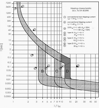
For the various applications three trip characteristics B, C and D are defined in IEC 60898 (Figure 1):

The tripping characteristics B, C and D under IEC 60898 are distinguished by the trip level of the short-circuit trigger

Figure 1 - The tripping characteristics B, C and D under IEC 60898 are distinguished by the trip level of the short-circuit trigger


The tripping characteristics B, C and D under IEC 60898 are distinguished by the trip level of the short-circuit trigger

  • Trip characteristic B is the standard characteristic for wall outlet circuits in domestic and utility buildings (I> ≥3 … 5*Ie)
  • Trip characteristic C is advantageous when using electrical equipment with higher inrush currents as for example of lamps and motors (I> ≥5 … 10*Ie)
  • Trip characteristic D is adapted to electrical equipment that can produce strong current surges such as transformers, electromagnetic valves or capacitors (I> ≥10 … 20*Ie)
AC miniature circuit breakers are normally suitable for single-phase and three-phase supplies up to a rated voltage of 240/415V and AC-DC MCB’s additionally for direct voltage supplies up to rated voltages of 125 V, 220 V or 440 V depending on the number of poles.

In addition to the quality of releasing according to the tripping characteristic, a key feature of MCB’s is their rated switching capacity. They are assigned to switching capacity classes, which indicate the maximum size of short-circuit current that can be handled.

Standard values under IEC 60898 are 1500, 3000, 4500, 6000, 10000, 20000 and 25000 A.

When selecting a MCB to protect cables and conductors, the permissible let-through-I2·t values for conductors must be respected. They may not be exceeded during clearing a short-circuit.

Therefore the I2·t values in relation to the prospective short-circuit current are important characteristic of MCB’s.

In some countries, miniature circuit breakers are classified according to the permissible I2·t values. According to the “Technical Connection Conditions” (TAB) of the German power utilities (EVU) for example only MCB’s with a rated switching capacity of at least 6000 A and the energy limitation Class 3 may be used for selectivity reasons in distribution boards of domestic and utility buildings behind the meter.

For industrial applications a switching capacity of 10000 A (10 kA) is usually required.


Installation of Miniature Circuit Breakers, safety clearances

MCB’s as components of installation systems are usually designed so that compliance with safety clearance requirements is assured when arranged conform to the system structure.

Circuit breakers can cope with very high currents at high voltages when breaking short-circuits.

MCB Safety clearances

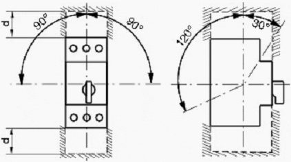
Figure 2 - It is essential that the safety clearances are observed. No conductive parts may be located within the hatched zones such as metallic walls or uninsulated conductors.


During the breaking process, the contact systems and arcing chambers consequently convert large amounts of power into heat energy.

In addition to high temperature rises of components such as contacts, de-ion plates and walls of the contact chambers, the energy converted into an arc results in heating of the air in the contact system to several thousand degrees Celsius and hence to the formation of a conductive plasma. This plasma is usually emitted through blow-out openings to the outside and must not reach any conductive parts to prevent secondary short-circuits.

For this season, safety clearances are specified for circuit breakers (Figure 2), within which no conductive parts – for example metallic walls or uninsulated conductors – may be located.

Frequently additional insulation components (phase partition walls or covers; in some cases optional) are used. With some products, additional insulation of the connected conductors is required in accordance with manufacturer specifications.

Non-compliance with the safety clearances can result in accidents with most severe consequences.


Example: Acti 9 MCB (VIDEO)

Cant see this video? Click here to watch it on Youtube.

Resource: Allen Bradley – Low Voltage Switchgear and Controlgear

Arrangements of LV Utility Distribution Networks (1)

$
0
0
Arrangements of LV Utility Distribution Networks

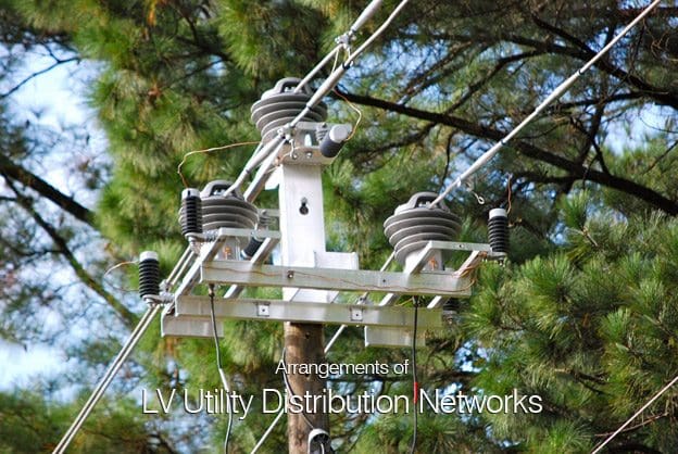
Arrangements of LV Utility Distribution Networks (photo credit to abbmvit.blogspot.com)

Introduction

In European countries the standard 3-phase 4-wire distribution voltage level is 230/400 V. Many countries are currently converting their LV systems to the latest IEC standard of 230/400 V nominal (IEC 60038).

Medium to large-sized towns and cities have underground cable distribution systems.

MV/LV distribution substations, mutually spaced at approximately 500-600 metres, are typically equipped with:

  1. A 3-or 4-way MV switchboard, often made up of incoming and outgoing load-break switches forming part of a ring main, and one or two MV circuit-breakers or combined fuse/ load-break switches for the transformer circuits
  2. One or two 1,000 kVA MV/LV transformers
  3. One or two (coupled) 6-or 8-way LV 3-phase 4-wire distribution fuse boards, or moulded-case circuit-breaker boards, control and protect outgoing 4-core distribution cables, generally referred to as “distributors

The output from a transformer is connected to the LV busbars via a load-break switch, or simply through isolating links. In densely-loaded areas, a standard size of distributor is laid to form a network, with (generally) one cable along each pavement and 4-way link boxes located in manholes at street corners, where two cables cross.

Recent trends are towards weather-proof cabinets above ground level, either against a wall, or where possible, flush-mounted in the wall. Links are inserted in such a way that distributors form radial circuits from the substation with open-ended branches (see Fig. C3).

Where a link box unites a distributor from one substation with that from a neighbouring substation, the phase links are omitted or replaced by fuses, but the neutral link remains in place.

Showing one of several ways in which a LV distribution network may be arranged

Fig. C3 : Showing one of several ways in which a LV distribution network may be arranged for radial branched-distributor operation, by removing (phase) links


This arrangement provides a very flexible system in which a complete substation can be taken out of service, while the area normally supplied from it is fed from link boxes of the surrounding substations.

Moreover, short lengths of distributor (between two link boxes) can be isolated for fault-location and repair. Where the load density requires it, the substations are more closely spaced, and transformers up to 1,500 kVA are sometimes necessary.

Other forms of urban LV network, based on free-standing LV distribution pillars, placed above ground at strategic points in the network, are widely used in areas of lower load density. This scheme exploits the principle of tapered radial distributors in which the distribution cable conductor size is reduced as the number of consumers downstream diminish with distance from the substation.

In this scheme a number of large-sectioned LV radial feeders from the distribution board in the substation supply the busbars of a distribution pillar, from which smaller distributors supply consumers immediately surrounding the pillar.

Distribution in market towns, villages and rural areas generally has, for many years, been based on bare copper conductors supported on wooden, concrete or steel poles, and supplied from pole-mounted or ground-mounted transformers.

In recent years, LV insulated conductors, twisted to form a two-core or 4-core self supporting cable for overhead use, have been developed, and are considered to be safer and visually more acceptable than bare copper lines. This is particularly so when the conductors are fixed to walls (e.g. under-eaves wiring) where they are hardly noticeable.

Improved methods using insulated twisted conductors to form a pole mounted aerial cable are now standard practice in many countriesAs a matter of interest, similar principles have been applied at higher voltages, and self supporting “bundled” insulated conductors for MV overhead installations are now available for operation at 24 kV. Where more than one substation supplies a village, arrangements are made at poles on which the LV lines from different substations meet, to interconnect corresponding phases.

North and Central American practice differs fundamentally from that in Europe, in that LV networks are practically nonexistent, and 3-phase supplies to premises in residential areas are rare.

The distribution is effectively carried out at medium voltage in a way, which again differs from standard European practices.

The MV system is, in fact, a 3-phase 4-wire system from which single-phase distribution networks (phase and neutral conductors) supply numerous single-phase transformers, the secondary windings of which are centre-tapped to produce 120/240 V single-phase 3-wire supplies.

In Europe, each utility-supply distribution substation is able to supply at LV an area corresponding to a radius of approximately 300 metres from the substation. North and Central American systems of distribution consist of a MV network from which numerous (small) MV/LV transformers each supply one or several consumers, by direct service cable (or line) from the transformer location

The central conductors provide the LV neutrals, which, together with the MV neutral conductors, are solidly earthed at intervals along their lengths. Each MV/LV transformer normally supplies one or several premises directly from the transformer position by radial service cable(s) or by overhead line(s).

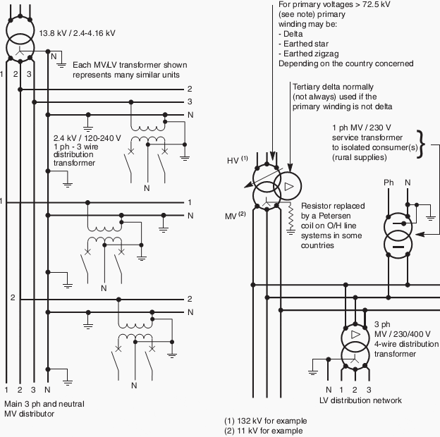
Many other systems exist in these countries, but the one described appears to be the most common. Figure C4 (in next part…) shows the main features of the two systems.

Will be continued…

Resource: Electrical Installation Guide 2009 – Schneider Electric

Arrangements of LV Utility Distribution Networks (2)

$
0
0
Arrangements of LV Utility Distribution Networks

Arrangements of LV Utility Distribution Networks (photo by Steve Ives @ Flickr: Street in Haddington, Philadelphia, PA, US)


Continued from the previous part: Arrangements of LV Utility Distribution Networks (1)


The consumer-service connection

In the past, an underground cable service or the wall-mounted insulated conductors from an overhead line service, invariably terminated inside the consumer’s premises, where the cable-end sealing box, the utility fuses (inaccessible to the consumer) and meters were installed.

A more recent trend is (as far as possible) to locate these service components in a weatherproof housing outside the building.

Widely-used American and European-type systems

Fig. C4: Widely-used American and European-type systems


Note: At primary voltages greater than 72.5 kV in bulk-supply substations, it is common practice in some European countries to use an earthed-star primary winding and a delta secondary winding. The neutral point on the secondaryside is then provided by a zigzag earthing reactor,the star point of which is connected to earth through a resistor. 

Frequently, the earthing reactor has a secondary winding to provide LV3-phase supplies for the substation. It is then referred to as an “earthing transformer”.

A MCCB  - moulded case circuit breaker which incorporates a sensitive residual-current earth-fault protective feature is mandatory at the origin of any LV installation forming part of a TT earthing system.

The utility/consumer interface is often at the outgoing terminals of the meter(s) or, in some cases, at the outgoing terminals of the installation main circuit-breaker (depending on local practices) to which connection is made by utility staff, following a satisfactory test and inspection of the installation.

A typical arrangement is shown in Figure C5.

Typical service arrangement for TT-earthed systems

Fig. C5: Typical service arrangement for TT-earthed systems


A further reason for this MCCB is that the consumer cannot exceed his (contractualdeclared maximum load, since the overload trip setting, which is sealed by the supply authority, will cut off supply above the declared value. Closing and tripping of the MCCB is freely available to the consumer, so that if the MCCB is inadvertently tripped on overload, or due to an appliance fault, supplies can be quickly restored following correction of the anomaly.

In view of the inconvenience to both the meter reader and consumer, the location of meters is nowadays generally outside the premises, either:

  • In a free-standing pillar-type housing as shown in Figures C6 and C7
  • In a space inside a building, but with cable termination and supply authority’s fuses located in a flush-mounted weatherproof cabinet accessible from the public way, as shown in Figure C8
  • For private residential consumers, the equipment shown in the cabinet in.
Typical rural-type installation

Fig. C6 : Typical rural-type installation


In this kind of installation it is often necessary to place the main installation circuit-breaker some distance from the point of utilization, e.g. saw-mills, pumping stations,  etc.


Semi-urban installations (shopping precincts, etc.)

Fig. C7: Semi-urban installations (shopping precincts, etc.)


The main installation CB is located in the consumer’s premises in cases where it is  set to trip if the declared kVA load demand is exceeded.


Town centre installations

Fig. C8: Town centre installations


The service cable terminates in a flushmounted wall cabinet which contains the  isolating fuse links, accessible from the public way. This method is preferred for  esthetic reasons, when the consumer can provide a suitable metering and main-switch location.


Typical LV service arrangement for residential consumers

Fig. C9: Typical LV service arrangement for residential consumers


Figure C5 is installed in a weatherproof cabinet mounted vertically on a metal frame in the front garden, or flush mounted in the boundary wall, and accessible to authorized personnel from the pavement.

Figure C9 shows the general arrangement, in which removable fuse links provide the means of isolation.

In the field of electronic metering, techniques have developed which make their use attractive by utilities either for electricity metering and for billing purposes, the liberalisation of the electricity market having increased the needs for more data collection to be returned from the meters.

For example electronic metering can also help utilities to understand their customers’ consumption profiles.

In the same way, they will be useful for more and more power line communication and radio-frequency applications as well.

In this area, prepayment systems are also more and more employed when economically justified. They are based on the fact that for instance consumers having made their payment at vending stations, generate tokens to pass the information concerning this payment on to the meters. For these systems the key issues are security and inter-operability which seem to have been addressed successfully now.

The attractiveness of these systems is due to the fact they not only replace the meters but also the billing systems, the reading of meters and the administration of the revenue collection.

Resource: Electrical Installation Guide 2009 – Schneider Electric

Lighting Circuits Connections for Interior Electrical Installations

$
0
0
Lighting Circuits Connections for Interior Electrical Installations

Lighting Circuits Connections for Interior Electrical Installations

Introduction

Electrical lines which include lighting circuits begin from the main distribution panel of the installation and each line contains three conductors: phase, neutral and ground. All three conductors reach to the terminal point of each luminaire and if it has a metal chassis the ground should be connected in the appropriate position.

From each main distribution panel at least two lighting supply lines are leaving, so a failure on one line does not sink the entire installation in the dark. Insulation on the conductors must show the colors required by the regulations.

The phase conductor must be brown or black, neutral conductor must be light blue and ground conductor must be yellow/green.

To understand the circuit connections we can use various designs, including the following:

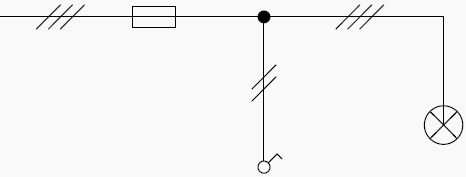
Single line diagram

Circuits shown are in the simplified form. These drawings show only the important elements of the lighting circuit and contain information on how to layout, number of the conductors and their cross – section.


Analytical diagram

Which show all the lines that connect the different parts of a circuit. These plans in large scale circuits can lose their figuration.


Operating diagram

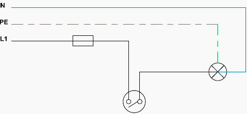
Which show in detail the paths of electrical current. This method of design is descriptive and easy to read.

1. Simply light circuit

Description:

Connection of one or more luminaire points (Lights) controlled by a simple switch. This kind of connection is used in almost all interior electrical installations.


General diagrams

Single line diagram

Simple light circuit - Single line diagram

Simple light circuit - Single line diagram


Analytical diagram

Simply light circuit - Analytical diagram

Simply light circuit - Analytical diagram

Operating diagram

Simply light circuit - Operating diagram

Simply light circuit - Operating diagram


Important Note:

In all lighting circuits a ground cable must be installed. Usually the luminaires for residential use belong in the next two categories:

  • Protection Class I: The device is grounded. The ground wire (yellow / green) must be connected to the clip marked with ground symbol.
  • Protection class II: The device is double insulated and cannot be connected to the ground.

Go to back to Content ↑

2. Selector switch lighting circuit (Comitater)

Description:

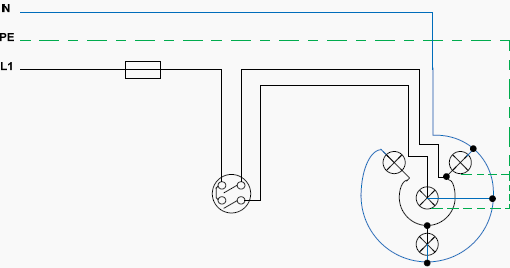
A connection of two groups of lamps controlled by a single point. The connection is usually used in chandeliers.


General diagrams

Single line diagram

Selector switch lighting circuit - Single line diagram

Selector switch lighting circuit - Single line diagram


Analytical diagram

Selector switch lighting circuit - Analytical diagram

Selector switch lighting circuit - Analytical diagram


Important Note:

During the design of various electrical circuits we pay attention to draw them in break mode (OFF), unless there are compelling reasons to the contrary. Above the circuit is ‘closed’, feeding all the lights.


Operating diagram

Selector switch lighting circuit - Operating diagram

Selector switch lighting circuit - Operating diagram


Go to back to Content ↑

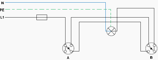
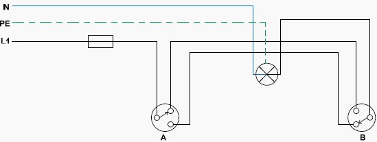
3. Two-way switching lighting circuit (Two extreme switches Aller–Retour)

Description:

Control of a lighting circuit from two points (A and B). This type of circuit is used in hallwaysrooms with two entrances, stairs, bedrooms, e.t.c.


General diagrams

Single line diagram

Two-way switching lighting circuit - Single line diagram

Two-way switching lighting circuit - Single line diagram

Analytical diagram

With rotary switches

Two-way switching lighting circuit - Analytical diagram with rotary switches

Two-way switching lighting circuit - Analytical diagram with rotary switches


With pushbutton switches

Two-way switching ighting circuit - Analytical diagram with pushbutton switches

Two-way switching ighting circuit - Analytical diagram with pushbutton switches

Operating diagram

With rotary switches

Two-way switching lighting circuit - Operating diagram with rotary switches

Two-way switching lighting circuit - Operating diagram with rotary switches


With pushbutton switches

Two-way switching lighting circuit - Operating diagram pushbutton switches

Two-way switching lighting circuit - Operating diagram pushbutton switches


Go to back to Content ↑

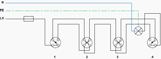
4. Switching lighting circuit (Aller–Retour) with two extreme switches and one or more intermediate switches

Description:

Control of a lighting circuit from three or more points. This type of circuit is used in large roomslong corridors, staircases and generally in large rooms.


General diagrams

Single line diagram

Switching lighting circuit - Single line diagram

Switching lighting circuit - Single line diagram


Analytical diagram

Switching lighting circuit - Analytical diagram

Switching lighting circuit - Analytical diagram

Operating diagram

Switching lighting circuit - Operating diagram

Switching lighting circuit - Operating diagram


Go to back to Content ↑

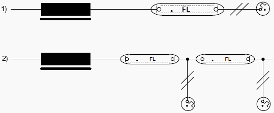
5. Lighting circuits with fluorescent tubes

Description:

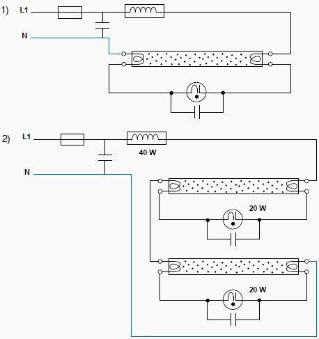
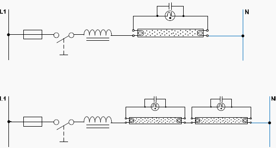
  1. Circuit of a 40W fluorescent tube, with 40W Ballast and starter.
  2. Circuit with two fluorescent tubes (20W each), with 40W Ballast and two starters (20W each)

The fluorescent tubes are used particularly in factories, offices, for decoration and advertising or promotion of goods. In recent years fluorescent tubes are used in residential installations.


General diagrams

Single line diagram

Fluorescent tubes - Single line diagram

Fluorescent tubes - Single line diagram


Important Note:

In figure b) we can add more fluorescent tubes if we want in series but we should also add more starters and a more powerful ballast.


Analitycal diagrams

Fluorescent tubes - Analytical diagram

Fluorescent tubes - Analytical diagram

Operating diagrams

Fluorescent tubes - Operating diagram

Fluorescent tubes - Operating diagram


Important Notes:

In figure 2) If one of the two starters or one of the two lamps stop working, then none of the lamps will eventually function.

The metal chassis of the lamp or the ballast’s choke should be grounded. The fluorescent tubes import reactive power to the grid. With new European Union directives, mechanical ballasts are repealed and only electronic ballasts (triac) should be used, which limit the reactive power.

The starter and the capacitor are abolished and we have direct ignition of the lamp.

Go to back to Content ↑

Lighting Circuits Connections for Interior Electrical Installations (2)

$
0
0
Light switch for interior installation

Light switch for interior installation


Continued from first part: Lighting Circuits Connections for Interior Electrical Installations


Introduction

In modern internal electrical installations, domestic and professional, there is a need for lighting installations in staircases and installation of emergency lighting that will operate in the event of interruption of electricity supply from the grid.

The automatic staircase timer abolished Aller – Retour switches to control the lighting of the staircase.

Of course, they can also be used as timers in other lighting and automation circuits (second consumption delay, e.g. bathroom ventilator, disengaging switch with a time delay).

Sometimes, a power failure might occur, due to a fault in the distribution network or due to maintenance issues. In some places such as hospitals, police and fire departments, cinemas and theatres, major hotels and conference rooms, this power outage has unpleasant results.

In order to address this problem, apart from the main lightning, we also manufacture an emergency lighting system which will be decribed in 3rd part of this technical article.


Automatic staircase timers

Single line diagrams, Analytical and Operating diagrams:

  1. Lighting circuit controlled by an automatic staircase timer (based on mercury)
  • Lighting circuit controlled by an automatic staircase timer (electronic)
  • 1. Lighting circuit controlled by an automatic staircase timer (based on mercury)

    Description:

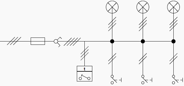
    Lighting circuit of a large number of luminaires, which is controlled by an automatic timer (interruption and restoration), operated by several points (instant contact pushbuttons). The circuit is mainly used in buildings staircases.

    Go up to the Timers ↑


    General diagrams

    Single line diagram

    Lighting circuit controlled by an automatic staircase timer

    Lighting circuit controlled by an automatic staircase timer - Single line diagram


    Important Note: We can connect in the circuit (always in parallel way) several lights and as many buttons as we desire.


    Analytical diagram

    Lighting circuit controlled by an automatic staircase timer - Analytical diagram

    Lighting circuit controlled by an automatic staircase timer - Analytical diagram


    Go up to the Timers ↑


    Operating mode

    Press any button and the coil is activated with the neutral being transferred through that button to the end of the coil. At the other end of the button the phase is applied through the medium contact (2) of the mercurial ampoule and the contact on the right end (3).

    Once activated the coil repels the armature (and the whole system) upward. Therefore the mercury bulb changes position shorting out the other two contacts (1) and (2).The phase is transferred to contact (1), namely the luminaires.

    The coil is not enabled as long as we let the button and the armature descends due to the weight of the cartridge cavity.

    The more closed the tap is, the more slowly the armature descends. This way we regulate the time the lights will stay on.

    Operating diagram

    Lighting circuit controlled by an automatic staircase timer - Operating diagram

    Lighting circuit controlled by an automatic staircase timer - Operating diagram


    Obcservations

    The automatic staircase timer (ΚΤ), is a combination of an alternative three position switch and a time relay. The positions of the alternative switch are:

    • 1st position: For automatic operation
    • 2nd position: Permanent discontinuation
    • 3rd position: Permanent operation (e.g. when we want to clean the stairway)

    Go up to the Timers ↑


    Automatic operation

    Pressing any instant contact pushbutton (B) , the control circuit closes and the time relay (KT) is stimulated, which subsequently and through the alternative switch closes the power circuit (main circuit), whereby lights illuminate. After a preselected time (as much needed to bring the hydraulic system of the timer in its rest position), power supply of the power circuit is turned off, by opening the contact KT1 of the time relay.

    Important note: By observing both the analytical and the operational diagram, we can see that the Neutral (N) is common for the luminaries and the pushbuttons.

    Go up to the Timers ↑


    2. Lighting circuit controlled by an automatic staircase timer (electronic)

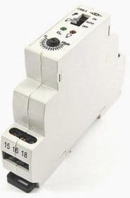
    Automatic staircase timer

    Automatic staircase timer


    Staircase timers are applied in any residential or commercial building wherever automatic control is required on predefined times.

    Lighting control in staircases made with automatic timers (bracket – rail profile), mounted in electrical switchboards at the staircase and activated by pushbuttons with light or no indication located in various places of the staircase or by motion detectors, which detect movements in the range of their surveillance and enable the automatic switch.

    Go up to the Timers ↑


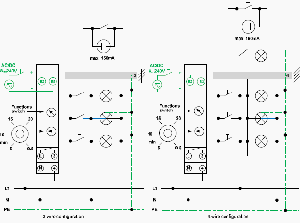
    2.1 Staircase electronic timer (3 and 4 wire configuration)

    Staircase electronic timer ( 3 & 4 wire configuration)

    Staircase electronic timer ( 3 & 4 wire configuration)

    Important Note: One contact of the lights is permanently connected to the Neutral and the other one is connected to the return (for the lights) of the automatic timer.

    Operation mode

    When you press any button the automatic timer is activated (the Neutral is carried through the button and at his edges 230V voltage is applied) and the main contact closes for as long as we have preselected. At that time the lights will illuminate. The phase is transferred through the main contact of the automatic timer to the other end of the luminaires.

    Once this time has elapsed, the contact opens and the lights go out.

    Important Note: One contact of the buttons is permanently connected to the Neutral and the other one is connected to the return (for the buttons) of the automatic timer.

    Go up to the Timers ↑


    2.2 Staircase electronic multifunctional timer (3 and 4 wire configuration)

    Staircase electronic multifunctional timer (3 and 4 wire configuration)

    Staircase electronic multifunctional timer (3 and 4 wire configuration)


    Automatic staircase timers are manufactured for certain lamp wattage.

    They have timers so we can choose the interval we want them to be turned on. The multifunctional automatic staircase timers have the option of continuous operation when a button is pressed for more than two seconds and they can increase and decrease their luminance for twenty seconds after the end of regulation time, as a warning that the lights will turn off.

    Also, they have the option (changeover switch) to pose the circuit off or keep the lights permanently on.

    Some of the automatic multifunctional timers may have separate control input 8 – 240 V AC/DC, galvanic separated (e.g. intercom) and they can also automatically detect the 3 or 4 wire configuration.

    Important note:

    The automatic staircase timers can be connected with incandescent lamps, halogen lamps, single fluorescent lamps and compact fluorescent electronic lamps.

    The electronic staircase automatic timers have some advantages over the older ones.

    The most important of these are:
    1. Wide range time adjustment.
    2. Great confidence when they work as there is no fear to get stuck while operating.
    3. High accuracy of repeatability of the time. Time does not change if no intervening setting.
    4. Their small size gives them the potential to be installed inside the staircase’s electrical panel.

    Go up to the Timers ↑

    Generalities and Discrimination Between RCDs

    $
    0
    0
    Generalities and Discrimination Between RCDs

    Generalities and Discrimination Between Residual Current Devices (RCDs)

    Generalities on Residual Current Circuit-Breakers

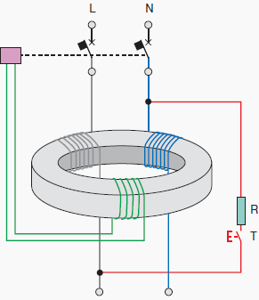
    The operating principle of the residual current release is basically the detection of an earth fault current, by means of a toroid transformer which embraces all the live conductors, included the neutral if distributed.

    In absence of an earth fault, the vectorial sum of the currents IΔ is equal to zero.

    In case of an earth fault, if the IΔ value exceeds the rated residual operating current IΔn, the circuit at the secondary side of the toroid sends a command signal to a dedicated opening coil causing the tripping of the circuit-breaker.

    Operating principle of the residual current device

    Figure 1 - Operating principle of the residual current device

    Classifications of RCDs

    A first classification of RCDs can be made according to the type of the fault current they can detect:

    1. AC type: the tripping is ensured for residual sinusoidal alternating currents, whether suddenly applied or slowly rising;
    2. A type: tripping is ensured for residual sinusoidal alternating currents and residual pulsating direct currents, whether suddenly applied or slowly rising;
    3. B type: tripping is ensured for residual direct currents, for residual sinusoidal alternating currents and residual pulsating direct currents, whether suddenly applied or slowly rising.

    Another classification referred to the operating time delay is:

    1. Undelayed type;
    2. Time delayed S-type.

    RCDs can be coupled, or not, with other devices; it is possible to distinguish among:

    1. Pure residual current circuit-breakers (RCCBs)
      They have only the residual current release and can protect only against earth fault. They must be coupled with thermomagnetic circuit-breakers or fuses, for the protection against thermal and dynamical stresses;
    2. Residual current circuit-breakers with overcurrent protection (RCBOs)
      They are the combination of a thermomagnetic circuit-breaker and a RCD; for this reason, they provide the protection against both overcurrents as well as earth fault current;
    3. Residual current circuit-breakers with external toroid
      They are used in industrial plants with high currents.

    They are composed by a release connected to an external toroid with a winding for the detection of the residual current; in case of earth fault, a signal commands the opening mechanism of a circuit-breaker or a line contactor.

    RCD Operation

    Given IΔn the operating residual current, a very important parameter for residual current devices is the residual non-operating current, which represents the maximum value of the residual current which does not cause the circuit-breaker trip; it is equal to 0.5 IΔn.

    Therefore, it is possible to conclude that:

    • for IΔ < 0.5⋅IΔn the RCD shall not operate;
    • for 0.5⋅IΔn < IΔ < IΔn the RCD could operate;
    • for IΔ > IΔn the RCD shall operate.

    For the choice of the rated operating residual current, it is necessary to consider, in addition to the coordination with the earthing system, also the whole of the leakage currents in the plant.

    Their vectorial sums on each phase shall not be greater than 0.5⋅IΔn. in order to avoid unwanted tripping.


    Discrimination between RCDs

    The Standard IEC 60364-5-53 states that discrimination between residual current protective devices installed in series may be required for service reasons, particularly when safety is involved, to provide continuity of supply to the parts of the installation not involved by the fault, if any.

    This discrimination can be achieved by selecting and installing RCDs in order to provide the disconnection from the supply by the RCD closest to the fault.

    There are two types of discrimination between RCDs:

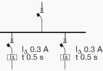
    Horizontal discrimination

    Horizontal discrimination between RCDs

    Figure 2 - Horizontal discrimination between RCDs


    It provides the protection of each line by using a dedicated residual current circuit-breaker; in this way, in case of earth fault, only the faulted line is disconnected, since the other RCDs do not detect any fault current.

    However, it is necessary to provide protective measures against indirect contacts in the part of the switchboard and of the plant upstream the RCD;


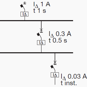
    Vertical discrimination

    Vertical discrimination between RCDs

    Figure 3 - Vertical discrimination between RCDs


    It is realized by using RCDs connected in series.

    Conditions

    According to IEC 60364-5-53, to ensure discrimination between two residual current protective devices in series, these devices shall satisfy both the following conditions:

    1. The non-actuating time-current characteristic of the residual current protective device located on the supply side (upstream) shall lie above the total operating time-current characteristic of the residual current protective device located on the load side (downstream);
    2. The rated residual operating current on the device located on the supply side shall be higher than that of the residual current protective device located on the load side.

    The Non-Actuating Time-Current Characteristic

    The non-actuating time-current characteristic is the curve reporting the maximum time value during which a residual current greater than the residual non-operating current (equal to 0.5.IΔn) involves the residual current circuit breaker without causing the tripping.

    As a conclusion, discrimination between two RCDs connected in series can be achieved:
    1. For S type residual current circuit-breakers, located on the supply side, (complying with IEC 61008-1 and IEC 61009), time-delayed type, by choosing general type circuit-breakers located downstream with IΔn equal to one third of IΔn of the upstream ones;
    2. For electronic residual current releases by choosing the upstream device with time and current thresholds directly greater than the downstream device, keeping carefully into consideration the tolerances.

    For the protection against indirect contacts in distribution circuits in TT system, the maximum disconnecting time at IΔn shall not exceed 1 s (IEC 60364-4-41, §413.1)

    Resource: Electrical Installation Handbook (part II) – ABB


    Differences Between Earthed and Unearthed Cables

    $
    0
    0
    Differences Between Earthed and Unearthed Cables

    Differences Between Earthed and Unearthed Cables

    Introduction

    In HT electrical distribution, the system can be earthed or unearthed.

    The selection of unearthed or earthed cable depends on distribution system. If such system is earthed, then we have to use cable which is manufactured for earthed system. (which the specifies the manufacturer). If the system is unearthed then we need to use cable which is manufactured for unearthed system.

    The unearthed system requires high insulation level compared to earthed system.

    For earthed and unearthed XLPE cables, the IS 7098 part2 1985 does not give any difference in specification. The insulation level for cable for unearthed system has to be more.


    Earthed System

    Earlier the generators and transformers were of small capacities and hence the fault current was less. The star point was solidly grounded. This is called earthed system.

    In three phases earthed system, phase to earth voltage is 1.732 times less than phase to phase voltage. Therefore voltage stress on cable to armor is 1.732 times less than voltage stress between conductors to conductor.

    Where in unearthed system, (if system neutral is not grounded) phase to ground voltage can be equal to phase to phase voltage. In such case the insulation level of conductor to armor should be equal to insulation level of conductor to conductor.

    In an earthed cable, the three phase of cable are earthed to a ground. Each of the phases of system is grounded to earth.

    Example: 1.9/3.3 KV, 3.8/6.6 KV system


    Unearthed System

    Today generators of 500MVA capacities are used and therefore the fault level has increased. In case of an earth fault, heavy current flows into the fault and this lead to damage of generators and transformers. To reduce the fault current, the star point is connected to earth through a resistance. If an earth fault occurs on one phase, the voltage of the faulty phase with respect to earth appears across the resistance.

    Therefore, the voltage of the other two healthy phases with respect to earth rises by 1.7 times.

    If the insulation of these phases is not designed for these increased voltages, they may develop earth fault. This is called unearthed system.

    In an unearth system, the phases are not grounded to earth .As a result of which there are chances of getting shock by personnel who are operating it.

    Example: 6.6/6.6 KV, 3.3/3.3 KV system.

    Unearthed cable has more insulation strength as compared to earthed cable. When fault occur phase to ground voltage is √3 time the normal phase to ground voltage. So if we used earthed cable in unearthed System, It may be chances of insulation puncture.

    So unearthed cable are used. Such type of cable is used in 6.6 KV systems where resistance type earthing is used.

    Nomenclature

    In simple logic the 11 KV earthed cable is suitable for use in 6.6 KV unearthed system. The process of manufacture of cable is same.

    The size of cable will depend on current rating and voltage level.

    • Voltage Grade (Uo/U) where Uo is Phase to Earth Voltage & U is Phase to Phase Voltage.
    • Earthed system has insulation grade of KV / 1.75 x KV.
    • For Earthed System (Uo/U): 1.9/3.3 kV, 3.8/6.6 kV, 6.35/11 kV, 12.7/22 kV and 19/33 kV.
    • Unearthed system has insulation grade of KV / KV.
    • For Unearthed System (Uo/U): 3.3/3.3 kV and 11/11 kV.
    • 3 phase 3 wire system has normally Unearthed grade cables and 3 phase 4 wire systems can be used earthed grade cables, insulation used is less, and cost is less.

    Thumb Rule

    As a thumb rule we can say that 6.6KV unearthed cable is equal to 11k earthed cable i.e 6.6/6.6kv Unearthed cable can be used for 6.6/11kv earthed system.

    Because each core of cable have the insulation level to withstand 6.6kv so between core to core insulation level will be 6.6kV+6.6kV = 11kV

    For transmission of HT, earthed cable will be more economical due to low cost where as unearthed cables are not economical but insulation will be good.

    Generally 6.6 kV and 11kV systems are earthed through a neutral grounding resistor and the shield and armor are also earthed, especially in industrial power distribution applications.  Such a case is similar to an unearthed application but with earthed shield (sometimes called solid bonding).

    In such cases, unearthed cables may be used so that the core insulation will have enough strength but current rating is de-rated to the value of earthed cables.

    But it is always better to mention the type of system earthing in the cable specification when ordering the cables so that the cable manufacturer will take care of insulation strength and de rating.

    Defining Size and Location of Capacitor in Electrical System (2)

    $
    0
    0
    Defining Size and Location of Capacitor in Electrical System (2)

    Defining Size and Location of Capacitor in Electrical System (2)


    Continued from part 1: Defining Size and Location of Capacitor in Electrical System (2)


    Content

    1. If no-load current is known
    2. If the no load current is not known
  • Placement of power capacitor bank for motor:
  • Placement of capacitors in distribution system:
  • Common capacitor reactive power ratings
  • Size of CB, Fuse and Conductor of Capacitor Bank

    A. Thermal and Magnetic setting of a Circuit breaker

    1. Size of Circuit Breaker

    1.3 to 1.5 x Capacitor Current (In) for Standard Duty/Heavy Duty/Energy Capacitors

    • 1.31×In for Heavy Duty/Energy Capacitors with 5.6% Detuned Reactor (Tuning Factor 4.3)
    • 1.19×In for Heavy Duty/Energy Capacitors with 7% Detuned Reactor (Tuning Factor 3.8)
    • 1.12×In for Heavy Duty/Energy Capacitors with 14% Detuned Reactor (Tuning Factor 2.7)
    Note: Restrictions in Thermal settings of system with Detuned reactors are due to limitation of IMP (Maximum Permissible current) of the Detuned reactor.

    2. Thermal Setting of Circuit Breaker

    1.5x Capacitor Current (In) for Standard Duty/Heavy Duty/Energy Capacitors


    3. Magnetic Setting of Circuit Breaker

    5 to 10 x Capacitor Current (In) for Standard Duty/Heavy Duty/Energy Capacitors

    Example: 150kvar,400v, 50Hz Capacitor

    • Us = 400V, Qs = 150kvar, Un = 400V, Qn = 150kvar
    • In = 150000/400√3 = 216A
    • Circuit Breaker Rating = 216 x 1.5 = 324A
    • Select a 400A Circuit Breaker.
    • Circuit Breaker thermal setting = 216 x 1.5 = 324 Amp

    Conclusion: Select a Circuit Breaker of 400A with Thermal Setting at 324A and Magnetic Setting (Short Circuit) at 324A

    Go to Content ↑


    B. Fuse Selection

    The rating must be chosen to allow the thermal protection to be set to:

    1.5 to 2.0 x Capacitor Current (In) for Standard Duty/Heavy Duty/Energy Capacitors.

    • 1.35×In for Heavy Duty/Energy Capacitors with 5.7% Detuned Reactor (Tuning Factor 4.3)
    • 1.2×In for Heavy Duty/Energy Capacitors with 7% Detuned Reactor (Tuning Factor 3.8)
    • 1.15×In for Heavy Duty/Energy Capacitors with 14% Detuned Reactor(Tuning Factor 2.7)

    For Star-solidly grounded systems:
    Fuse > = 135% of rated capacitor current (includes overvoltage, capacitor tolerances, and harmonics).

    For Star -ungrounded systems:
    Fuse > = 125% of rated capacitor current (includes overvoltage, capacitor tolerances, and harmonics).

    Care should be taken when using NEMA Type T and K tin links which are rated 150%. In this case, the divide the fuse rating by 1.50.

    Example 1: 150kvar,400v, 50Hz Capacitor

    • Us = 400V; Qs = 150kvar, Un = 400V; Qn = 150kvar.
    • Capacitor Current =150×1000/400 =375 Amp

    To determine line current, we must divide the 375 amps by √ 3

    • In (Line Current) = 375/√3 = 216A
    • HRC Fuse Rating = 216 x1.65 = 356A to
    • HRC Fuse Rating = 216 x 2.0 = 432A so Select Fuse Size 400 Amp

    Go to Content ↑


    Problems with Fusing of Small Ungrounded Banks

    Example: 12.47 kV, 1500 Kvar Capacitor bank made of three 3 No’s of 500 Kvar single-phase units.

    • Nominal Capacitor Current = 1500/1.732×12.47 = 69.44 amp
    • Size of Fuse = 1.5×69.44 = 104 Amp = 100 Amp Fuse

    If a capacitor fails, we say that It may approximately take 3x line current. (3 x 69.44 A = 208.32 A).

    It will take a 100 A fuse approximately 500 seconds to clear this fault (3 x 69.44 A = 208.32 A). The capacitor case will rupture long before the fuse clears the fault.

    The solution is using smaller units with individual fusing. Consider 5 No’s of 100 kVAR capacitors per phase, each with a 25 A fuse. The clear time for a 25 A fuse @ 208.32 A is below the published capacitor rupture curve.

    Go to Content ↑


    C. Size of Conductor for Capacitor Connections

    Size of capacitor circuit conductors should be at least 135% of the rated capacitor current in accordance with NEC Article 460.8 (2005 Edition).

    Go to Content ↑


    Size of capacitor for Transformer No-Load compensation

    Fixed compensation

    The transformer works on the principle of Mutual Induction. The transformer will consume reactive power for magnetizing purpose. Following size of capacitor bank is required to reduce reactive component (No Load Losses) of Transformer.

    Selection of capacitor for transformer no-load compensation
    KVA Rating of the TransformerKvar Required for compensation
    Up to and including 315 KVA5% of KVA Transformer Rating
    315 to 1000 KVA6% of KVA Transformer Rating
    Above 1000 KVA8% of KVA Transformer Rating

    Go to Content ↑


    Sizing of capacitor for motor compensation

    The capacitor provides a local source of reactive current. With respect to inductive motor load, this reactive power is the magnetizing or “no load current“ which the motor requires to operate.

    A capacitor is properly sized when its full load current rating is 90% of the no-load current of the motor. This 90% rating avoids over correction and the accompanying problems such as overvoltages.

    Go to Content ↑


    1. If no-load current is known

    The most accurate method of selecting a capacitor is to take the no load current of the motor, and multiply by 0.90 (90%).

    Example:

    Size a capacitor for a 100HP, 460V 3-phase motor which has a full load current of 124 amps and a no-load current of 37 amps.

    Size of Capacitor = No load amps (37 Amp) X 90% = 33 Kvar

    Go to Content ↑


    2. If the no load current is not known

    If the no-load current is unknown, a reasonable estimate for 3-phase motors is to take the full load amps and multiply by 30%. Then multiply it by 90% rating figure being used to avoid overcorrection and overvoltages.

    Example:

    Size a capacitor for a 75HP, 460V 3-phase motor which has a full load current of 92 amps and an unknown no-load current.

    No-load current of Motor = Full load Current (92 Amp) x 30% = 28 Amp estimated no-load Current.

    Size of Capacitor = No load amps (28 Amp) X 90% = 25 Kvar.

    Thumb Rule:

    It is widely accepted to use a thumb rule that Motor compensation required in kvar is equal to 33% of the Motor Rating in HP.

    Go to Content ↑


    Placement of Power Capacitor Bank for Motor

    Capacitors installed for motor applications based on the number of motors to have power factor correction. If only a single motor or a small number of motors require power factor correction, the capacitor can be installed at each motor such that it is switched on and off with the motor.

    Go to Content ↑


    Required Precaution for selecting Capacitor for Motor:

    The care should be taken in deciding the Kvar rating of the capacitor in relation to the magnetizing kVA of the machine.

    If the rating is too high, It may damage to both motor and capacitor.

    As the motor, while still in rotation after disconnection from the supply, it may act as a generator by self excitation and produce a voltage higher than the supply voltage. If the motor is switched on again before the speed has fallen to about 80% of the normal running speed, the high voltage will be superimposed on the supply circuits and there may be a risk of damaging other types of equipment.

    As a general rule the correct size of capacitor for individual correction of a motor should have a kvar rating not exceeding 85% of the normal No Load magnetizing KVA of the machine. If several motors connected to a single bus and require power factor correction, install the capacitor(s) at the bus.

    Go to Content ↑


    Where do not install Capacitor on Motor:

    Do not install capacitors directly onto a motor circuit under the following conditions:

    1. If solid-state starters are used.
    2. If open-transition starting is used.
    3. If the motor is subject to repetitive switching, jogging, inching, or plugging.
    4. If a multi-speed motor is used.
    5. If a reversing motor is used.
    6. If a high-inertia load is connected to the motor.

    Fixed power capacitor banks can be installed in a non-harmonic producing electrical system at the feeder, load or service entrance. Since power capacitor banks are reactive power generators, the most logical place to install them is directly at the load where the reactive power is consumed.

    Three options exist for installing a power capacitor bank at the motor.

    Installing a power capacitor bank at the motor

    Installing a power capacitor bank at the motor

    Go to Content ↑


    Location 1 (The line side of the starter)

    Install between the upstream circuit breaker and the contactor.

    This location should be used for the motor loads with high inertia, where disconnecting the motor with the power capacitor bank can turn the motor into a self excited generator, motors that are jogged, plugged or reversed, motors that start frequently, multi-speed motors, starters that disconnect and reconnect capacitor units during cycling and starters with open transition.

    Advantage

    Larger, more cost effective capacitor banks can be installed as they supply kvar to several motors. This is recommended for jogging motors, multispeed motors and reversing applications.

    Disadvantages

    • Since capacitors are not switched with the motors, overcorrection can occur if all motors are not running.
    • Since reactive current must be carried a greater distance, there are higher line losses and larger voltage drops.

    Applications

    • Large banks of fixed kVAR with fusing on each phase.
    • Automatically switched banks

    Go to Content ↑


    Location 2 (Between the overload relay and the starter)

    Install between the contactor and the overload relay.

    • This location can be used in existing installations when the overload ratings surpass the National Electrical Code requirements.
    • With this option the overload relay can be set for nameplate full load current of motor. Otherwise the same as Option 1.
    • No extra switch or fuses required.
    • Contactor serves as capacitor disconnect.
    • Change overload relays to compensate for reduced motor current.
    • Too much Kvar can damage motors.
    Calculate new (reduced) motor current. Set overload relays for this new motor FLA.

    FLA (New) = P.F (Old) / P.F (New) x FLA (Name Plate)

    Application:

    Usually the best location for individual capacitors.

    Go to Content ↑


    Location 3 (The motor side of the overload relay)

    Install directly at the single speed induction motor terminals (on the secondary of the overload relay).

    • This location can be used in existing installations when no overload change is required and in new installations in which the overloads can be sized in accordance with reduced current draw.
    • When correcting the power factor for an entire facility, fixed power capacitor banks are usually installed on feeder circuits or at the service entrance.
    • Fixed power capacitor banks should only be used when the facility’s load is fairly constant. When a power capacitor bank is connected to a feeder or service entrance a circuit breaker or a fused disconnect switch must be provided.
    • New motor installations in which overloads can be sized in accordance with reduced current draw
    • Existing motors when no overload change is required.

    Advantage

    • Can be switched on or off with the motors, eliminating the need for separate switching devices or over current protection. Also, only energized when the motor is running.
    • Since Kvar is located where it is required, line losses and voltage drops are minimized; while system capacity is maximized.

    Disadvantages

    • Installation costs are higher when a large number of individual motors need correction.
    • Overload relay settings must be changed to account for lower motor current draw.

    Application

    Usually the best location for individual capacitors.

    Go to Content ↑


    Placement of capacitors in Distribution system

    The location of low voltage capacitors in Distribution System effect on the mode of compensation, which may be global (one location for the entire installation), by sectors (section-by-section), at load level, or some combination of the last two.

    In principle, the ideal compensation is applied at a point of consumption and at the level required at any instant.

    Placement of capacitors in distribution system

    Placement of capacitors in distribution system


    Go to Content ↑


    A. Global compensation

    Principle

    The capacitor bank is connected to the bus bars of the main LV distribution board to compensation of reactive energy of whole installation and it remains in service during the period of normal load.

    Advantages

    • Reduces the tariff penalties for excessive consumption of kvars.
    • Reduces the apparent power kVA demand, on which standing charges are usually based
    • Relieves Reactive energy of Transformer , which is then able to accept more load if necessary

    Limitation

    • Reactive current still flows in all conductors of cables leaving (i.e. downstream of) the main LV distribution board. For this reason, the sizing of these cables and power losses in them are not improved by the global mode of compensation.
    • The losses in the cables (I2R) are not reduced.

    Application

    • Where a load is continuous and stable, global compensation can be applied
    • No billing of reactive energy.
    • This is the most economical solution, as all the power is concentrated at one point and the expansion coefficient makes it possible to optimize the capacitor banks
    • Makes less demands on the transformer.

    Go to Content ↑


    B. Compensation by sector

    Principle

    Capacitor banks are connected to bus bars of each local distribution Panel.

    Most part of the installation System can benefits from this arrangement, mostly the feeder cables from the main distribution Panel to each of the local distribution panel.

    Advantages

    • Reduces the tariff penalties for excessive consumption of kvar.
    • Reduces the apparent power Kva demand, on which standing charges are usually based.
    • The size of the cables supplying the local distribution boards may be reduced, or will have additional capacity for possible load increases.
    • Losses in the same cables will be reduced.
    • No billing of reactive energy.
    • Makes less demands on the supply Feeders and reduces the heat losses in these Feeders.
    • Incorporates the expansion of each sector.
    • Makes less demands on the transformer.
    • Remains economical

    Limitations

    • Reactive current still flows in all cables downstream of the local distribution Boards.
    • For the above reason, the sizing of these cables, and the power losses in them, are not improved by compensation by sector
    • Where large changes in loads occur, there is always a risk of overcompensation and consequent overvoltage problems.

    Application

    Compensation by sector is recommended when the installation is extensive, and where the load/time patterns differ from one part of the installation to another.

    This configuration is convenient for a very widespread factory Area, with workshops having different load factors

    Go to Content ↑


    C. Individual compensation

    Principle

    • Capacitors are connected directly to the terminals of inductive circuit (Near to motors). Individual compensation should be considered when the power of the motor is significant with respect to the declared power requirement (kVA) of the installation.
    • The kvar rating of the capacitor bank is in the order of 25% of the kW rating of the motor.
    • Complementary compensation at the origin of the installation (transformer) may also be beneficial.
    • Directly at the Load terminals Ex. Motors, a Steady load gives maximum benefit to Users.
    • The capacitor bank is connected right at the inductive load terminals (especially large motors). This configuration is well adapted when the load power is significant compared to the subscribed power. This is the technical ideal configuration, as the reactive energy is produced exactly where it is needed, and adjusted to the demand.

    Advantages

    • Reduces the tariff penalties for excessive consumption of kvars
    • Reduces the apparent power kVA demand
    • Reduces the size of all cables as well as the cable losses.
    • No billing of reactive energy
    • From a technical point of view this is the ideal solution, as the reactive energy is produced at the point where it is consumed. Heat losses (RI2) are therefore reduced in all the lines.
    • Makes less demands on the transformer.

    Limitations

    • Significant reactive currents no longer exist in the installation.
    • Not recommended for Electronics Drives.
    • Most costly solution due to the high number of installations.
    • The fact that the expansion coefficient is not incorporated.

    Application

    Individual compensation should be considered when the power of motor is significant with respect to power of the installation.

    Go to Content ↑


    Common Capacitor Reactive Power Ratings

    VoltageKvar RatingNumber of Phases
    2165, 7.5, 131/3, 20, 251 or 3
    2402.5, 5, 7.5,10, 25, 20, 25, 501 or 3
    4805, 10, 15, 20 25, 35, 50, 60, 1001 or 3
    6005, 10, 15, 20 25, 35, 50, 60, 1001 or 3
    2,40050, 100, 150, 2001
    2,77050, 100, 150, 2001
    7,20050, 100, 150, 200,300,4001
    12,47050, 100, 150, 200,300,4001
    13,80050, 100, 150, 200,300,400

    Go to Content ↑

    Using AC switchgear in DC applications

    $
    0
    0
    Using AC switchgear in DC applications

    Using AC switchgear in DC applications (photo by Kaleo Construction)

    Skin effect

    Switchgear designed for alternating current can carry at least the same rated continuous operational DC current. With direct current the skin effect in the circuits disappears and none of the specific effects associated with alternating currents such as hysteresis or eddy current losses occur.

    DC devices that are operated at low voltage can be switched by AC switchgear without difficulty, as their direct current switching capacity at low voltages is practically the same as for alternating current.

    With voltages in excess of around 60 V, the direct current switching capacity of AC switchgear with double-breaking contacts (for example contactors) decreases strongly.

    By connecting two or three circuits in series (Figure 1) this limit can be raised to twice or three times the voltage.

    Examples of diagrams for poles connected in series

    Figure 1 - Examples of diagrams for poles connected in series


    Where grounded power supplies are used (top graph) with loads switched on both sides, it should be noted that ground faults can lead to bridging of contacts and hence to a reduction in the breakable voltage.

    The reason for the reduced switching capacity with DC compared with AC is the absence of the current zero crossover that with AC supports the quenching of the electric arc.

    The electric arc in the contact system can continue to burn under larger direct voltages and thus destroy the switchgear. With direct voltages, the contact erosion and hence also the contact life span differ from those at alternating voltage. The attainable values for direct current are specifically tested and documented.

    With direct current, the load affects the switching capacity more strongly than with alternating current.

    The energy stored in the inductance of the load must largely be dissipated in the form of an electric arc.

    Hence with a strongly inductive load (large time constant L/R) the permissible switching capacity for the same electrical life span is smaller than with an ohmic load due to the much longer breaking times.


    Overload release units

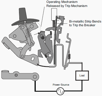
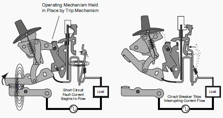
    Thermal-magnetic circuit breakers employ a bi-metalic strip to sense overload conditions.

    Thermal-magnetic circuit breakers employ a bi-metalic strip to sense overload conditions.


    The reaction of bimetal strips heated by the operating current depends on the heat generated in the bimetal strips and intheir heating coil, if any.

    This applies equally for alternating current and direct current.

    The trip characteristic can be somewhat slower with direct current as there are no hysteresis and eddy current losses.

    With overload releases that are sensitive to phase failure, all three circuits should always be connected in series to prevent premature tripping.

    Overload releases heated via current transformers are not suitable for direct current. Also electronic overload relays in most cases cannot be used in direct current applications as the current is measured via current transformers and their functionality is tailored to alternating current.


    Short-circuit releases

    Short Circuit Trip

    Short Circuit Trip


    Electromagnetic overcurrent releases can be used with direct current. However the tripping threshold current is somewhat higher than with alternating current.


    Undervoltage and shunt-trip releases

    Undervoltage and shunt-trip releases operate with magnet circuits. Special designs are required for direct voltage.

    Resource: Allen Bradley – Low Voltage Switchgear and Controlgear

    Switching contactor and effect of long control lines

    $
    0
    0
    Switching contactor and effect of long control lines

    Switching contactor and effect of long control lines

    Voltage drop

    In accordance with IEC 60947-4-1 and IEC 60947-5-1, the normal control voltage range of power and control contactors lies between 85 … 110 % of the rated control voltage. Within these limits contactors pull-in perfectly.

    Frequently contactors are offered with an extended control voltage range, thus for example with contactors with electronic coil control. The technical documentation of the devices used is definitive.

    At small control voltages and with long control lines, the voltage drop across the lines to the contactor (both out-going and return conductors should be considered!) can be so big that pulling-in reliably is no longer guaranteed. In addition to burnt coils, another consequence of this may be welding of the main contacts.

    It must therefore be ensured that taking into account:
    1. Supply voltage variations
    2. Voltage drop at the control transformer at peak load and
    3. Voltage drop across the control lines the minimum pull-in voltage is always guaranteed.

    For the voltage drop across the control lines the following applies approximately:

    Voltage drop across the control lines

    or for the maximum line length at a given permissible voltage drop:

    Maximum line length at a given permissible voltage drop

    • l – Line length (supply and return line) [m]
    • lmax - maximum line length (feeding and return line) [m]
    • uR - Percentage voltage drop [%]
    • UC – Rated control voltage [V]
    • S – Pickup power of the contactor [VA] κ Conductivity of the conductor material [m·Ω-1·mm-1] = 57 for copper
    • A – Conductor cross section [mm2]
    Line lengths for a voltage drop of 5 % and copper conductors

    Figure 1 - Line lengths for a voltage drop of 5 % and copper conductors


    l – Line length (feeding and return line)
    S – Apparent power of load


    Effect of the cable capacitance

    With AC controls with long control lines, low coil power ratings of the contactors and high control voltage, depending on the topography of the circuit, the capacitance of the control line can be in parallel to the controlling contact and practically bypass it when it is open.

    This can mean that when the control contact has opened sufficient current continues to flow via the cable capacitance causing the contactor not to drop out. An example may be a contactor that is controlled by a distantly located sensor (for example limit-switch).

    When the control contact switches off the cable to the contactor, the capacitance of the line causes at most a slight drop-off delay.

    Figure 2 - When the control contact switches off the cable to the contactor, the capacitance of the line causes at most a slight drop-off delay.


    If the long control line to the contactor stays live when the control contact is open, the current via the cable capacitance can prevent the contactor from dropping out. With pulse contact control, the capacitance of the lines acts twice, whereby the permissible line length is halved.

    Figure 3 - If the long control line to the contactor stays live when the control contact is open, the current via the cable capacitance can prevent the contactor from dropping out. With pulse contact control, the capacitance of the lines acts twice, whereby the permissible line length is halved.


    A worked example would be:

    I= 0.25 ICN
    U= 0.6 UC
    cos φ = 0.3

    IH – Holding current of the contactor
    ICN – Rated current the contactor coil
    UH – Drop-out voltage of the contactor
    UC – Control voltage
    cos φ – Power factor of the contactor coil (on-state)

    The permissible cable capacitance is calculated at 50 Hz approximately to be:

    CZ ≈ 500 · SH/UC2 [μF]

    CZ - Permissible cable capacitance [μF]
    SH – Holding power at UC[VA]
    UC – Control voltage [V]

    At a typical cable capacitance of 0.3 μF/km the permissible line length for maintained contact control is:

    Permissible line length formaintained contact control

    With momentary contact control the line length is halved. Graphic presentation for the control voltages 110 V and 230 V see Figure 4. As the cable capacitance is very much dependent on the type of cable, it is recommended in case of doubt to obtain the specific value from the manufacturer or to measure it.

    Permissible line length in accordance with the above conditions for maintained contact control at control voltages of 110 V and 230 V at 50 Hz

    Figure 4 - Permissible line length in accordance with the above conditions for maintained contact control at control voltages of 110 V and 230 V at 50 Hz


    l – Line length
    S – Apparent power (holding power) of the contactor

    If there are problem with respect to the permissible line length because of the line capacitance the following measures are possible in accordance with above discussion:
    • Application of an additional load (resistor parallel to contactor coil)
    • Use of a larger contactor with bigger holding power
    • Use of a lower control voltage
    • Use of direct voltage

    Reference: Allen Bradley Low Voltage Switchgear and Controlgear // Rockwell Automation

    Example of MV/LV network structure with dual fed main MV switchboard

    $
    0
    0
    MV dual fed switchboard with 2/3 type transfer

    MV dual fed switchboard with 2/3 type transfer


    Connected to article: Example of standard MV/LV network structure

    Network structure:

    • MV consumer substation;
    • The main MV switchboard can be backed up by a generator set and it feeds two MV/LV transformers;
      MV switchboard can be GIS or AIS and consist of following cubicles:
      - two incoming feeders (from utility)
      - two transformer cubicles
      - bus riser and bus coupling cubicle(s)
      - two outgoing transformer cubicles (supplying LV switchboard)
      - two cubicles connected to generators for backup power supply 
    • The main low voltage switchboard has a dual power supply with coupler;
    • Each bus section of the main low voltage switchboard has a UPS system feeding a priority circuit;
    • The secondary switchboards, terminal boxes and motor control centers are fed by a single source.

    Reference: Protection of Electrical Networks - Christophe Prévé 

    What affects the operating temperature within LV switchgear

    $
    0
    0
    What affects the operating temperature within LV switchgear

    What affects the operating temperature within LV switchgear

    Maximum ambient condition

    BS EN 60439 states a maximum indoor ambient temperature of 40ºC, a maximum daily average of 35ºC and a minimum ambient of -5ºC.

    As a general guidance rule, the temperature within the low voltage switchgear should not exceed 50/55ºC. If Switchroom/Plant room ambients are typically considered to be up to 25°C this relates to a 25/30K rise above ambient. In the maximum ambient condition of 40ºC, this relates to a 10/15K rise above ambient.

    Natural ventilation facilities will be required in the design of the switchboard to ensure the maximum internal temperature is not exceeded.

    The sources of heat within the low voltage switchgear will be:

    1. Heat liberated by the copperwork and cabling.
    2. Heat liberated by the devices.
    3. Heat liberated by eddy currents and magnetic losses.

    A LV switchgear accommodates a number of devices in a configuration that relates to the scheme requirements. The enclosure and compartments within it provide the operating environment for each device.

    Most devices e.g. circuit breakers, fuse switches, contactors etc. have been Type Tested in free air or “other enclosures”.

    When enclosed within an LV switchgear compartment the heat liberated may adequately dissipate by convection and radiation from the “walls” of the enclosure and by heat sink via the conductors. It may however be necessary to assist the liberation to atmosphere by forced ventilation.

    LV switchgear compartments (photo credit: Eaton)

    LV switchgear compartments (photo credit: Eaton)


    Devices, which invariably require such measures, have by experience been found to be:

    • ACB’s above 2,500A
    • PFC Capacitor Banks
    • Variable Speed Drives
    • Motor Starting Resistors
    • Power Transformers

    Natural ventilation via louvres and/or mesh screens are the simplest and most cost effective measure of controlling temperature rise provided that I.P. ratings are agreed with the client.

    The problems arising from eddy currents and magnetic losses are generally overcome by common good practice in the selection of appropriate non-ferrous materials and the avoidance of ferrous metal “magnetic loops” being created in structures in close proximity to conductors or groups of conductors where phase/neutral balance may not prevail.

    The subject of these sources of heat is often considered as one but is in fact two separate issues.

    Eddy Current heating results from the I2R losses of induced currents circulating in metalwork, which is not part of the defined conductor system. The use of non magnetic, low resistance materials such as Aluminium and Brass for single core cable gland plates and equipment mounting back plates (e.g. for circuit breakers above 630A) will reduce this source of heat and is advisable.

    Typical hysteresis loop and magnetic domain morphology og ferromagnetic materials

    Typical hysteresis loop and magnetic domain morphology og ferromagnetic materials (illustration credit: electronenergy.com)


    Magnetic Heating results from the energy dissipated through each cycle of magnetization and de magnetization of a ferrous material (hysteresis loss) and relates to the metalurgical specification of the material used.

    Both these issues and the losses associated with them are frequency related and will be adversely affected at frequencies above the fundamental (50Hz).

    Ferrous metal “magnetic loops” around single conductors or groups of conductors that do not produce a magnetic nil balance can bring about additional problems to those mentioned above by virtue of the fact that currents are circulating in metallic structures and joints in them that are not designed as conductor systems. These currents can be of extremely high magnitude, particularly during short-term load inrush transients and during short circuit conditions.

    Such high current circulations through joints in the structures can result in arcing / sparking at such joints. The arcing can produce an ionised gaseous state in a region close to the main conductors / busbars and precipitate a most catastrophic flashover and destructive failure in this zone of the switchboard.

    In situations where mechanical support is required between conductors, non-magnetic materials and sometimes non-metallic materials, have to be applied.

    Forced ventilation with fans

    Forced ventilation with fans


    Forced ventilation via fan(s) will have to be considered if natural ventilation will not adequately maintain an acceptable environment for the device(s). Fans should be arranged to provide positive pressure (blowing in at low level) with exhaust air discharging at high level.

    It is generally advisable to use fans with integral louver/filter housings regardless of the I.P. requirements.

    In situations where the I.P. rating of fan ventilated systems is not acceptably high enough or the temperature rise cannot be adequately controlled by this method – Refrigerated (A/C) cooling techniques must be employed.

    Anti-condensation control may have to be incorporated either resulting from specified requirements or if the operating environment requires it. This may be catered for by thermostatically controlled heaters and/or ventilation.

    Special anti-condensation paint on internal surfaces is also effective in some cases.

    Reference: Technical Considerations in the Specification of LV Switchboards – AF SWITCHGEAR & CONTROL PANELS LIMITED

    Harmonic Distortion and High Frequency Applications

    $
    0
    0
    Harmonic Distortion and High Frequency Applications

    Harmonic Distortion and High Frequency Applications (on photo: Switchgear busbar; by satinamerican.com)

    Distortion of the fundamental sine wave

    The presence of harmonic frequencies in addition to the fundamental 50Hz, bring about distortion of the fundamental sine wave. Considerable problems may arise dependant upon the level of this distortion.

    Sources of harmonic distortion can be:

    1. Variable Speed Drives
    2. UPS equipment
    3. Non linear load (switch mode power supplies)
    4. Special industrial processes
    5. Resonant conditions with PFC capacitors
    6. Diesel generated supplies, cyclic engine/flywheel irregularities and full pitch winding alternators.
    A particularly problematic manifestation of the presence of harmonic currents is the reduced level of current depth of penetration in all conductors (switchgear, transformers, cabling etc) known as Skin Effect at the higher frequencies.

    The Copper Development Association has produced two useful documents (publications 22 and 123), which include information relating to power quality and system reliability. The following formula, taken from publication 22 can be used to establish the depth of penetration in flat copper bar for various frequencies:

    Depth of penetration,

    Depth of penetration in flat copper bar

    Where:

    • d – depth of penetration [mm]
    • ρ – resistivity of copper [μς cm]
    • f – frequency [Hz]

    Example at fundimental, 50hz:

    Fundimental 50Hz

    Examples at some harmonic frequencies:

    HarmonicFrequency (Hz)Depth of penetration (mm)
     3rdf = 150Hzd = 5.38
     5thf = 250Hzd = 4.18
     7thf = 350Hzd = 3.52
     11thf = 550Hzd = 2.81
     13thf = 650Hzd = 2.85

    It can be seen that at 50Hz the penetration depth is just over 9mm therefore with conductors (or solid laminations) greater than 18mm thick, the centre of the conductor starts to be “void” of current. As the higher frequencies are considered e.g. the 13th (650Hz) the centre of 6mm thick conductors is not being “reached”.

    This definitely results in higher conductor temperatures than those expected under true sinusoidal conditions, encourages the use of conservatively rated copperwork and the adoption of air spaced conductor laminations rather than solid, butt-up, formations.

    A further problem arises with harmonic currents in that unlike “normal” fundamental currents, the odd numbered i.e. 3rd, 5th, 7th etc. etc. harmonic currents do not vectorially add with a resultant as the neutral current – they arithmetically add and summate in the neutral.

    This can result in neutral currents exceeding those of the phase currents.

    Reference: Technical Considerations in the Specification of LV Switchboards – AF Swichgear


    10 Important Precautions When Working On Low Voltage Energized Equipment

    $
    0
    0
    10 Important Precautions When Working On Low Voltage Energized Equipment

    10 Important Precautions When Working On Low Voltage Energized Equipment (photo credit: pacificsource.net)

    Have eyes in the back of head…

    For most work, the electrical equipment must be de-energized because there is a high risk of injury to workers if they work on energized equipment. It may be possible to schedule such work outside of normal work hours to limit the inconvenience.

    Sometimes it is not practicable to completely disconnect low-voltage equipment before working on it.

    For example, it may be necessary to have equipment running in order to test it or fine-tune it. In such cases, the work must be performed by workers who are qualified and authorized to do the work. They must follow written safe work procedures.

    You should observe the following important precautions when working on energized equipment, but note that these are not a substitute for proper training and written safe work procedures:

    1. Think ahead

    Assess all of the risks associated with the task. Plan the whole job in advance so that you can take every precaution, including arranging for help in case of paralyzing shock. Consider the use of a pre-job safety meeting to discuss the job with all workers before starting the work.


    2. Know the system

    Accurate, up-to-date information should be available to those who work on the system. This means that you should know all equipment installed according to the valid documentation (technical specifications, single line diagrams, wiring diagrams, block schemes etc.).

    Be careful, sometimes equipment stated in documentation can differ from the one installed on site – due to the replacing of old (damaged) equipment with the new with similar characteristics.


    3. Limit the exposure

    Have live parts exposed for as little time as necessary. This does not mean that you should work hastily. Be organized so that the job can be done efficiently.


    4. Cover exposed live metal

    Use insulating barriers or shields to cover live parts. Plexiglas plates can be usefull.


    5. Cover grounded metalwork

    Grounded metal parts should be covered with insulating material as much as possible. Very important.


    6. Limit the energy to reduce the risk

    All practical steps should be taken to ensure that the fault current at the point of work is kept as low as possible while the work is in progress. For example, when measuring voltage, do it on the load side of the circuit-protective devices with the smallest current rating.

    Current-limiting devices can be used to reduce the risk of an arc flash.


    7. Remove metal stuff

    These could cause a short-circuit where small clearances are involved. (If it is necessary to wear medic-alert bracelets, secure them with transparent surgical or adhesive tape or rubber bands.)


    8. One hand, face and body to side

    Use one hand with your face and body turned to the side when operating a safety switch. Limit possible injuries by not placing body parts directly in front of energized equipment when there is danger of an arc flash.


    9. When you’re in awkward positions…

    Avoid electrical contact when working in awkward positions. If you must work in an awkward or unbalanced position and reach with your tools, use insulating cover-up material on the tools to avoid contact with live conductors.


    10. Equipment and clothing

    Use the correct safety equipment and clothing. Remeber: gloves, clothes and shoes.

    Safety clothes, gloves and shoes

    Safety clothes, gloves and shoes


    Reference: Electical Safety at Low Voltage - penticton.ca

    Methods Of Mounting LV Circuit Breakers

    $
    0
    0
    Methods Of Mounting LV Circuit Breakers

    Methods Of Mounting LV Circuit Breakers

    Three general groups

    Methods used to mount circuit breakers can be divided into three general groups, those being:

    1. Fixed
    2. Removable (disconnectable unit), and
    3. Drawout (withdrawable)

    A review of these mounting methods follows.


    Fixed Mounted Circuit Breakers

    Siemens fixed air circuit breaker

    Siemens fixed air circuit breaker


    A circuit breaker that is bolted in its enclosure and wired to the load frame, we can call a fixed mounted circuit breaker. These units are typically rated 600 volts or less and are front mountable. Power is provided to the breaker typically by wires or sectional type bus bars.

    Power feeding the circuit breaker must be turned off in order to physically remove the fixed mounted breaker.

    Go back to Topics ↑


    Removable Mounted Circuit Breakers (Disconnectable units)

    Removable disconnectable circuit breaker

    Removable disconnectable circuit breaker (photo credit: electrical-installation.org)


    A removable circuit breaker (Disconnectable unit) has two parts, a base, which is bolted to and wired to the frame, and the actual breaker, which has insulated parts that electrically mate with the base. This means of mounting allows the unit to be replaced with out re-wiring the unit on the line side of the breaker.

    This type of mounting is typically used for breakers rated 600 volts or less.

    Go back to Topics ↑


    Drawout (Withdrawable) Mounted Circuit Breakers

    Withdrawable Circuit Breaker

    Withdrawable Circuit Breakers (on photo: ABB’s Emax Low voltage air circuit-breaker)


    A drawout circuit breaker also has two parts, the base, which is bolted and wired to the frame and the actual breaker, which slides into and electrically mates with the base. This allows the unit to be replaced without having to turn off the power feeding the breaker.

    The load must be turned off in order to test, remove or replace the unit.

    As a safety feature these units are interlocked to automatically turn the power off just before removal of the breaker begins. By design, only the circuit breaker’s load must be turned off to remove the breaker. This method of mounting allows for a single breaker to be disconnected from the power supply.

    That is to say that it does not require that all of the power be disconnected from all of the breakers installed in the larger enclosure such as a motor control center.

    There are various designs used to facilitate the “racking-in”(installation) and “racking out”(withdrawal) of the drawout type circuit breaker. Commonly some form of jacking screw is used to initially move and thus electrically disengage the breaker, then a traveling trolley type of hoist (somewhat like a small boat winch) supports the breaker during removal and re-installation.

    A transient supporting device is necessary as these sizes of breakers are too heavy and too bulky to be safely moved into and out of position by one person.

    Go back to Topics ↑

    Reference: Electrical Circuit Breakers – L.W. BRITTIAN Mechanical & Electrical Instructor

    Methods Of Securing LV Circuit Breakers

    $
    0
    0
    Methods Of Securing Circuit Breakers

    Methods Of Securing Circuit Breakers (photo credit: Schneider Electric; Acti 9 miniature circuit breakers range)

    Methods

    Circuit breakers are typically secured in place by one of the following methods:


    Bolted Type Breakers

    3P 50A 600V Bolt-on with lugs breaker by SIEMENS

    3P 50A 600V Bolt-on with lugs breaker by SIEMENS


    When a longer service life breaker is wanted, a bolted type is typically used. These types have a metal tab (one for each phase) sticking out from one end that is bolted to the busbar with a machine screw (bolt type fine threads and not sheet metal screw type steep pitch threads).

    When replacing these types of breakers, the retaining bolts or machine screws will have power on them unless power to the entire panelboard has been removed.

    It is not un-common for some individuals to initially determine that it is necessary to replace these types of breakers with power still applied to the busbars. I am not a big fan of working any thing above 12 volts hot, for I have witnessed too many good folks get hurt doing what was initially anticipated as being a quick and simple task.

    When this type of breaker must be replaced with power still applied to the busbars, it should be done only under strict safety procedures; using proper personnel protective equipment and double insulated tools (every day plastic handle screwdrivers must not be used). A detailed job safety analysis should be conducted before any hot work is undertaken.

    On more than one occasion I have witnessed some truly professionals conducting rehearsals of this type of activity several times until each safety step was done correctly. Take the time you need to be safe.

    Go back to Index ↑


    Stab Lock Type Breakers

    Federal Pacific Stab-lok (NA) Circuit Breaker

    Federal Pacific Stab-lok (NA) Circuit Breaker


    This type of breaker employs a male-female type of plug & receptacle connection to a metal busbar on one end. The opposite end of the breaker is mated to the enclosure housing and does not make electrical contact with the busbar.

    These types of breakers are found in homes and light commercial applications installed in loadcenters. With this method of mounting some movement of the breaker is normal.

    This small amount of breaker case movement is typically 1/8 of an inch or less on the busbar end. The circuit conductor termination lug may also exhibit some minor movement of the termination lug; again normally this movement is less than about 1/8 of an inch.

    Go back to Index ↑


    Din Rail Mounted Breakers

    DIN rail mounted circuit breaker

    DIN rail mounted circuit breaker


    With this method, a mounting rail is secured to the enclosure and the breaker is snapped onto the mounting rail. This allows for replacement to be made quickly as the device can be un-clipped and a new one clipped on to the DIN rail.

    Conductors for the supply and load are typically secured to the breaker using pressure connectors that are tightened by some type of threaded fastener.

    While not as easy to replace as Stab Lock Type Breakers This type of breaker employs a male-female type of plug and receptacle connection to a metal busbar on one end. The opposite end of the breaker is mated to the enclosure housing and does not make electrical contact with the busbar.

    These types of breakers are found in homes and light commercial applications installed in loadcenters. With this method of mounting some movement of the breaker is normal.

    This small amount of breaker case movement is typically 1/8 of an inch or less on the busbar end. The circuit conductor termination lug may also exhibit some minor movement of the termination lug; again normally this movement is less than about 1/8 of an inch.

    Go back to Index ↑

    Reference: Electrical Circuit Breakers – L.W. BRITTIAN Mechanical & Electrical Instructor

    Rating Definitions Applied to Low Voltage Molded-Case Circuit Breaker (MCCB)

    $
    0
    0
    Rating Definitions Applied to Low Voltage Molded-Case Circuit Breaker (MCCB)

    Rating Definitions Applied to Low Voltage Molded-Case Circuit Breaker (MCCB)

    For system protection 600V and below

    The molded-case circuit breaker is the “workhorse” for system protection 600V and below. A circuit breaker is a device designed to open and close by nonautomatic means and to open the circuit automatically on a predetermined overcurrent without damage to itself when properly applied within its rating.

    The following terms apply to molded-case circuit breakers:


    Voltage - Circuit breakers are designed and marked with the maximum voltage at which they can be applied. Circuit breaker voltage ratings distinguish between delta-connected, 3-wire systems and wye-connected, 4-wire systems.

    As stated in NEC article 240.85, a circuit breaker with a straight voltage rating, such as 240 or 480 V can be used in a circuit in which the nominal voltage between any two conductors does not exceed the circuit breaker’s voltage rating.

    Breakers with slash ratings, such as 120/240 V or 480 Y/277 V, can be applied in a solidly-grounded circuit where the nominal voltage of any conductor to ground does not exceed the lower of the two values of the circuit breaker’s voltage rating and the nominal voltage between any two conductors does not exceed the higher value of the circuit breaker’s voltage rating.

    Frequency - Molded-case circuit breakers are normally suitable for 50Hz or 60Hz. Some have DC ratings as well.

    Continuous current or Rated current - This is the maximum current a circuit breaker can carry continuously at a given ambient temperature rating without tripping (typically 40˚C).

    In accordance with NEC article 210.20 a circuit breaker (or any branch circuit overcurrent device) should not be loaded to over 80% of its continuous current unless the assembly, including the circuit breaker and enclosure, is listed for operation at 100% of its rating.

    PolesThe number of poles is the number of ganged circuit breaker elements in a single housing. Circuit breakers are available with one, two, or three poles, and also four poles for certain applications.

    Per NEC article 240.85 a two-pole circuit breaker cannot be used for protecting a 3-phase, corner-grounded delta circuit unless the circuit breaker is marked 1ø – 3ø to indicate such suitability.

    Control voltageThe control voltage rating is the AC or DC voltage designated to be applied to control devices intended to open or close a circuit breaker. In most cases this only applies to accessories that are custom-ordered, such as motor operators.


    Interrupting rating - This is the highest current at rated voltage that the circuit breaker is intended to interrupt under standard test conditions.

    Short-time or Withstand RatingThis characterizes the circuit-breaker’s ability to withstand the effects of short-circuit current flow for a stated period. Molded-case circuit breakers typically do not have a withstand rating, although some newer-design breakers do.

    Instantaneous overrideA function of an electronic trip circuit breaker that causes the instantaneous function to operate above a given level of current if the instantaneous function characteristic has been disabled.

    Current Limiting Circuit BreakerThis is a circuit breaker which does not employ a fusible element and, when operating in its current-limiting range, limits the let-through I2t to a value less than the I2t of a _-cycle wave of the symmetrical prospective current.

    HIDThis is a marking that indicates that a circuit breaker has passed additional endurance and temperature rise tests to assess its ability to be used as the regular switching device for high intensity discharge lighting. Per NEC 240.80 (D) a circuit breaker which is used as a switch in an HID lighting circuit must be marked as HID.

    HID circuit breakers can also be used as switches in fluorescent lighting circuits.

    SWDThis is a marking that indicates that a circuit breaker has passed additional endurance and temperature rise tests to assess its ability to be used as the regular switching device fluorescent lighting.

    Per NEC 240.80 (D) a circuit breaker which is used as a switch in an HID lighting circuit must be marked as SWD or HID.

    FrameThe term Frame is applied to a group of circuit breakers of similar configuration. Frame size is expressed in amperes and corresponds to the largest ampere rating available in that group.

    Thermal-magnetic circuit breakerThis type of circuit breaker contains a thermal element to trip the circuit breaker for overloads and a faster magnetic instantaneous element to trip the circuit breaker for short circuits.

    On many larger thermal-magnetic circuit breakers the instantaneous element is adjustable.

    Electronic trip circuit breakerAn electronic circuit breaker contains a solid-state adjustable trip unit. These circuit breakers are extremely flexible in coordination with other devices.

    SensorAn electronic-trip circuit breaker’s sensor is usually an air-core current transformer (CT) designed specifically to work with that circuit breaker’s trip unit.

    The sensor size, in conjunction with the rating plug, determines the electronic-trip circuit breaker’s continuous current rating.

    Rating plugAn electronic trip circuit breaker’s rating plug can vary the circuit breaker’s continuous current rating as a function of it’s sensor size.

    Typical molded-case circuit breakers are shown in Figure 1, where on the left is a thermal-magnetic circuit breaker, and on the right is an electronic-trip circuit breaker. The thermal-magnetic circuit breaker is designed for cable connections and the electronic circuit breaker is designed for bus connections, but neither type is inherently suited for one connection type over another.

    Circuit breakers may be mounted in stand-alone enclosures, in switchboards, or in panelboards.

    Molded-Case circuit breakers

    Figure 1 – Molded-Case circuit breakers

    Thermal-magnetic circuit breaker time-current characteristic

    A typical thermal-magnetic circuit breaker time-current characteristic is shown in figure 2.

    Note the two distinct parts of the characteristic curve: The thermal or long-time characteristic is used for overload protection and the magnetic or instantaneous characteristic is used for short-circuit protection.

    Note also that there is a band of operating times for a given fault current. The lower boundary represents the lowest possible trip time and the upper boundary represents the highest possible trip time for a given current.

    Thermal magnetic circuit breaker time-current characteristic

    Figure 2 – Thermal magnetic circuit breaker time-current characteristic

    Electronic-trip circuit breaker time-current characteristic

    The time-current characteristic for an electronic-trip circuit breaker is shown in figure 3. The characteristic for an electronic trip circuit breaker consists of the long time pickup, long-time delay, short-time pickup, short time delay, and instantaneous pickup parameters, all of which are adjustable over a given range.

    This adjustability makes the electronic-trip circuit breaker very flexible when coordinating with other devices. The adjustable parameters for an electronic trip circuit breaker are features of the trip unit.

    In many cases the trip unit is also available without the short-time function.

    In catalog data the long-time characteristic is listed as L, the short-time is listed as S, and the instantaneous as I. Therefore an LSI trip unit has long-time, short-time, and instantaneous characteristics, whereas an LI trip unit has only the long-time and instantaneous characteristics.

    For circuit breakers that have a short-time rating, the instantaneous feature may be disabled, enhancing coordination with downstream devices.

    Electronic-trip circuit breaker time-current characteristic

    Figure 3 – Electronic-trip circuit breaker time-current characteristic


    If the instantaneous feature has been disabled one must still be cognizant of any instantaneous override feature the breaker has, which will engage the instantaneous function above a given level of current even if it has been disabled in order to protect the circuit breaker from damage.


    Coordination

    Typical coordination between an electronic and a thermal magnetic circuit breaker is shown in figure 4 below. Because the time bands do not overlap, these two devices are considered to be coordinated.

    Typical molded-case circuit breaker coordination

    Figure 4 – Typical molded-case circuit breaker coordination


    A further reduction in the let-through energy for a fault in the region between two electronic-trip circuit breakers can be accomplished through zone-selective interlocking. This consists of wiring the two trip units such that if the downstream circuit breaker senses the fault (typically this will be based upon the short-time pickup) it sends a restraining signalto the upstream circuit breaker.

    The upstream circuit breaker will then continue to time out as specified on its characteristic curve, tripping if the downstream device does not clear the fault.

    However, if the downstream device does not sense the fault and the upstream devices does, the upstream device will not have the restraining signal from the downstream device and will trip with no intentional delay.

    Example

    For example, if zone selective interlocking were present in the system of figure 4 and fault occurs on bus C circuit breaker B will sense the fault and send a restraining signal to circuit breaker A. Circuit breaker A is coordinated with circuit breaker B, so circuit breaker B will trip first.

    If circuit breaker B fails to clear the fault, circuit breaker A will time out on its time-current characteristic per figure 4 and trip. If the fault occurs at bus B, circuit breaker B will not detect the fault and thus will not send the restraining signal to circuit breaker A. Circuit breaker A will sense the fault and will trip with no intentional delay, which is faster than dictated by its time-current characteristic per figure 4.

    Care must be used when applying zone-selective interlocking where there are multiple sources of power and fault currents can flow in either direction through a circuit breaker.

    Table 1 shows typical characteristics of molded-case circuit breakers for commercial and industrial applications. This table is for reference only; when specifying circuit breakers manufacturer’s actual catalog data should be used.

    Frame Size (A)Number of
    Poles
    Interrupting Rating at AC voltage (kA, RMS symmetrical)
    120 V240 V277 V480 V600 V
    10011014
    16565
    100, 1502, 3181414
    2, 3652518
    2, 31006525
    225, 2502, 3252222
    2, 3652522
    2, 31006525
    400, 6002, 3423022
    2, 3656525
    2, 310035
    800, 10003423022
    655025
    20010065
    12003423022
    3655025
    320010065
    1600, 20003655042
    312510065
    3000, 4000310010085
    3200150100

    Note that the continuous current rating is set by the sensor and rating plug sizes for a given electronic-trip circuit breaker. This can be smaller than the frame size. As can be seen from table 1, more than one interrupting rating can be available for a given frame size.

    Current-limiting circuit breakers are also available. Coordination between two current-limiting circuit breakers when they are both operating in the current limiting range is typically determined by test.

    By definition, low voltage molded case circuit breakers are not maintainable devices. Failure of a component generally requires replacement of the entire circuit breaker unless the circuit breaker has been specifically designed for maintainability.

    Magnetic-only circuit breaker swhich have only magnetic tripping capability are available. These are often used as short-circuit protection for motor circuits. For this reason these are often referred to as motor circuit protectors.

    Reference: System Protection – Bill Brown, P.E., Square D Engineering Services

    Guidelines to Maintenance of Low Voltage Switchboard

    $
    0
    0
    Guidelines to Maintenance of Low Voltage Switchboard

    Guidelines to Maintenance of Low Voltage Switchboard (photo credit: ikmichaniki.gr)

    Maintenance Benefits and Facilities

    A. Maintenance Program

    A well-executed maintenance program can provide the following benefits:

    1. Longer life of switchboard and fewer replacements;
    2. Reduced time on repairs and overhauls, and the option of scheduling them at an opportune time;
    3. Fewer failures with unexpected outages;
    4. Timely detection of any undesirable operating conditions which require correction;
    5. Improved plant performance and increased operating economies

    B. Maintenance Records

    A maintenance file should be established which should include the following:

    1. A record of all installed switchboards and their maintenance schedule;
    2. Nameplate data of all the equipment and its major components, instruction books, renewal parts lists, bulletins and drawings;
    3. A list of all items which have to be inspected and what adjustments are to be checked;
    4. A record of past inspections and test results.

    C. Maintenance Tests

    Maintenance tests are applicable as indicated:

    1. Insulation resistance tests of the switchboards’ breakers and bus can be useful in determining the condition of the insulation if they are performed regularly. Since definite limits cannot be given for satisfactory insulation resistance, a record must be kept of the readings and comparisons made. Deterioration of insulation and the need for corrective action can be recognized if the readings are progressively lower after each test.

    2. High potential tests are not required and are not recommended except in special circumstances, such as after repairs or modifications to the equipment that included the primary circuit (bus assemblies).

      When such tests are necessary, they may be conducted using 75% of the standard 60-cycle test voltage for new equipment.
      Hi-Pot test is a contraction for high potential HV testing.

      Hi-Pot test is a contraction for high potential HV testing.


    3. After the switchboard has been serviced and adjusted, its operation should be checked before it is returned to service.
      This can best be done by putting the breaker in the test position (if drawout) and operating it with its associated control and protective devices from a separate source or supply.
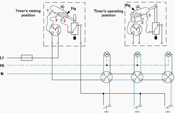
    D. Maintenance Equipment

    Adequate maintenance equipment should include:

    1. Spare parts for at least those parts of the switchboard that are vital to operation. The manufacturer’s recommended list of spare parts can be used as a guide in combination with operating experience to determine variety and quantity of parts to be stocked.

    2. A well equipped shop with the following:
      • A test cabinet or inspection rack for power circuit breakers;
      • A source of control power for checking the operation of electrically-operated breakers;
      • A selection of test instruments – multimeters, clamp-on ammeters, instrument transformers;
      • Lifting means for handling large breakers;
      • An insulation resistance tester (Megger™, Fluke™ or equivalent).
    Fluke insulation resistance tester up to 10kV

    Fluke insulation resistance tester up to 10kV – Allows testing of high voltage systems such as control gears, engines, generators and cables. It can be adjusted to all testing voltages that are specified in IEEE 43-2000. Ideal for Electricity Board and industrial companies for predictive and preventive maintenance.

    E. Safety Considerations

    Only authorized and properly trained personnel should be permitted to operate or handle any part of the switchboard.

    Maintenance employees must follow all recognized safety practices such as those contained in the National Electrical Safety Code and in Company or other local safety regulations during maintenance.
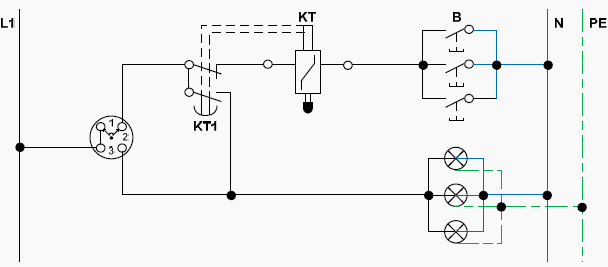
    All of the units of the switchboard to be maintained must be de-energized, tested for potential, grounded and tagged out before removing covers and barriers for access to primary circuits.

    Keep in mind that power circuit breakers are also capable of storing mechanical energy in the form of contact closing springs. Make sure breakers are open and springs are properly discharged and/or blocked before working on the mechanism. Always refer to the breaker’s maintenance manual for specific safety considerations.

    F. Frequency of Inspection & Test

    It is generally good practice to inspect equipment three to six months after it is first put in service and then inspect and maintain it every one to three years depending on its service and operating conditions. This suggested schedule is only a guide.

    Low voltage switchgear maintenance

    Low voltage switchgear maintenance (photo credit: elcome.com)


    Conditions that can make more frequent maintenance necessary are:

    1. High humidity and ambient temperatures;
    2. Corrosive atmosphere;
    3. Excessive dirt and dust;
    4. High repetitive duty;
    5. Frequent interruption of faults;
    6. Older equipment;
    7. History on preceding inspections

    Reference: Switchboard Installation and Maintenance Manual – Industrial Electric Mfg

    Viewing all 182 articles
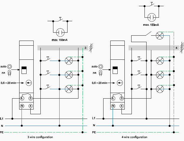
    Browse latest View live