7 Practical Tips For Installing a Good Measuring System (on photo: ABB’s low voltage switchgear type MNS; by controlequipment.ie)
1. Start from the need: what do I want to measure?
A single electric parameter or all the electric parameters
There are different product families on the market: instruments that measure a single electric parameter (voltage, current, frequency, phase angle cosϕ), generally used in single phase systems, as instrumentation on the machine, and instruments that enable all the electric parameters to be measured and displayed, both for the single phase and in the three-phase system.
This type of multifunction instrument is ideal in panels in which space is limited, in panels of substations and in main industrial panels.
If not only electric parameters need to be monitored but also energy consumption needs to be checked, measuring instruments that also include an active and reactive energy count have to be selected.
2. Selecting the measuring system
Single parameter, multifunction, analogue or digital instrument
Multi-Functional Power Meter (photo credit: powermeterstore.com)
The instrument should be selected according to the type of distribution system. In a single-phase system, analogue and digital instruments are selected for measuring voltage, current, frequency and the power factor.
In a three-phase system instruments can be installed that measure the single electric parameter, one per phase, or a voltmeter and an current can be installed together with the voltage and current switches, which enable the measurements to be displayed in sequence, phase by phase.
Choosing an analogue instrument ensure good reading stability, due to the mechanical inertia of the needle and the fact that the reader immediately knows whether the instrument is working normally or whether the reading is off-scale.
The analogue instrument indicates the point on the measuring scale in which it finds itself, showing the upper and lower limits.
In digital instruments this indication is not possible as the only reference is the reading of the value on the display, for example, of the current. Some measuring instruments have bar indicators that show the current level as a percentage of the set full scale.
Choosing a digital instrument guarantees better readability, also in poor lighting, specially for instruments with LED displays, and an immediate reaction to the measurement variation.
3. Sizing the system, choosing the CT
Sizing the measuring system starts with knowing the main parameters of the plant; in particular, starting from the characteristics of the protection switch, the type of distribution system, rated current, rated voltage and bar type can be known.
Current transformers used in metering equipment for 3-phase 400A electricity supply (photo credit: Wikipedia)
After the type of instrument has been defined that is most suitable for requirements, if the measurement is conducted through indirect insertion, the accessories of the measuring system such as current and voltage transformers must be chosen carefully.
If an 800 A current has to be measured, in most cases the instrument cannot be connected directly to the line. A current transformer that is suitable for the application must therefore be selected. The chosen parameters of a current transformer are not only rated current, secondary current and power but also the type of assembly. Flexible and stiff cables or bars for carrying power can be installed in a power panel.
The transformers can be of different types, depending on the assembly system: a through cable or a cable with a wound primary, transformers for assembly on horizontal or vertical bars.
4. Cabling and wiring diagrams
Connecting analogue instruments is very simple; it in fact suffices to connect the phase and neutral cables to the instrument’s.terminal. Two cables fo the auxiliary supply must always be connected for digital instruments.
Power meter series 800 – wire connection with 3 CTs and no PT
Multifunction instruments can be used in different distribution systems.
In three-phase systems with distributed neutral three current transformers are required. In three-phase systems without distibuted neutral in which the loads are balanced and symmetrical, an aron insertion can be carried out, i.e. two current transformers rather than three can be used; the instrument will calculate by difference the third phase that is not measured directly, considering it to be the same as the other two.
In multifunction instruments not only the cables connected to the measurement, but also the RS485 serial port and the analogue and digital outputs and inputs have to be cabled.
5. Protecting the instrument and earthing
In order to ensure that the instrument is properly protected, fuses must always be fitted to the supply cables of digital instruments and to the voltmeter measuring inputs.
Earthing the secondaries of the CTs ensures an earth connection if the transformer develops a fault and does not affect the measurement. If there is a great potential difference between neutral and earth, this could affect the measurement negatively, in the case of instruments with measuring inputs that are not galvanically insulated.
6. Setting digital instruments
Before digital instruments start operating they must be set with the parameters of the measuring system and the communication parameters. The main measuring parameters are the transformation ratios of the CTs and of the VTs, which are defined as the mathematical ratio between the nominal value and the value of the secondary;
For example, setting the transformation ratio of an CT CT3/100 with a secondary at 5 A means setting kCT = 100: 5 = 20
7. Troubleshooting during final testing
The main problems that arise during the test phase may be due to incorrect installation of the instruments and the accessories. Always check that the wiring complies with the instruction manual.
Errors during installation
The following errors are those that are most frequently committed when installing a measuring instrument:
Inverting the secondaries of the CTs
Inverting the phases of the current and voltage measuring inputs
Failure to eliminate the short circuit of the secondaries of the CTs
Setting an incorrect transformer ratio.
Reference: Practical guide to electrical measurements in low voltage switchboards – ABB (Download)
Electrical life (durability) of LV circuit breakers due to the switching operations (photo credit: unilec.net)
Test requirements
According to the standard IEC 947-2, there is actually no defined stipulation regarding the requirements of electrical life of a circuit breaker. The numbers of switching operations which a circuit breaker under no-load, normal load, overload and short-circuit conditions has to make and/or break are stipulated.
These numbers vary between two switchings (O-t-CO) for the rated ultimate short-circuit breaking capacity test and a few thousand purely mechanical operations under no-load condition.
Practical aspect
The electrical life or durability (life of the contact tips) of a circuit breaker, similar to a contactor, depends mainly on the magnitude of the breaking current (neglecting the contact erosion due to bouncing during the making operation, which is kept at a minimum with appropriate constructive measures).
Short Circuit Trip
Lower currents in the range of normal service conditions or overloads in the range of the thermally delayed release mechanism has very little influence on the contact life in comparison with the effect of the short-circuit currents of the order of the breaking capacity. Due to a few high current short-circuits close to the bus bars, the electrical erosion of the contacts could be so high that the circuit breaker may have to be replaced.
However, practical experience shows that the magnitude of the short-circuit currents would be rarely of the order of 50 kA or higher. They usually lie much lower in their amplitudes and the contact erosion is also within reasons.
In the case of a circuit breaker which is already installed, it is not easily visible from outside how many short-circuits it has already interrupted or what the actual amplitudes of the short-circuit currents were and whether the circuit breaker has already reached the end if its electrical life.
In spite of the above, the circuit breaker indicates indirectly when it has reached the end of its useful life. The thermal overload release tends to trip earlier, already at the rated value of the current setting on the scale. Thus the protective function of the device remains fully active right up to the end of its life.
The reason of the early tripping is because of the higher temperature-rise of the current path already at the rated current due to the increased contact resistance of the strongly eroded main contacts. In the long run, it affects the tripping characteristic of the thermal release. Early tripping is the result.
A circuit breaker which can no longer continuously carry its normal rated current indicates that the contact resistance is too high (electrically eroded contacts). They have reached the end of their electrical life and are to be replaced.
In other words, the circuit breaker remains reliable and safe up to the end. A normal operation indicates that the circuit breaker is functionally in order. If there is no early tripping after the breaker is switched on, it signifies that it can interrupt a short-circuit as well.
Inspection, Test and Measurement Procedures for LV and MV (up to 36kV) Switchgears (on photo” Eaton Cutler Hammer Magnum DS Switchgear Inspection, and Transformer Testing)
Importance of checks and maintenance
Installed in clean, well ventilated or air-conditioned locations, switchgear will require little routine maintenance.
Major inspection should be scheduled for power plant shutdowns and concentrate for low voltage switchboards on identifying contact wear, correct operation of interlocks, correct overload settings and fuse sizes, signs of overheating, and undue dirt or corrosion. For MV switchgear similar considerations apply although more extensive checks on protective devices, circuit breaker oil, vacuum bottle contact distances are required as specified by the Manufacturer.
Exceptions to the above rule are devices which operate frequently, where inspection/overhaul may need to be based on the number of operations. Also, MV isolating devices which have cleared a short circuit will require confirmation that the insulating medium and the circuit contacts are fit for continued service.
Gas Insulated Switchgear (GIS) shall be maintained in accordance with the manufacturer’s recommendations. Where extensive (intrusive) maintenance is required, the Manufacturer should be involved in the activity.
For older switchgear, a condition assessment should be performed to establish that the equipment remains in a suitable condition for further service.
Partial discharge testing and infrared scanning can be used to obtain data on the performance of the insulation system and the integrity of the switchgear busbars and cable terminations. The frequency of such tests will depend on the duty, age and condition of the switchgear.
The effectiveness of infra-red scanning depends on the ability to access the current-carrying components under loaded condition. Scanning through metallic enclosures has generally proved ineffective. Removal of enclosures of live equipment may not be possible without compromising electrical safety.
LV switchgear
Type
Description
Interval
Extent
1. INSPECTION
General external condition.
1 y
All
Motor starters and outgoing feeders, internal. Incomers, internal.
4 y
Busbar compartments (1).
8 y
Metering: - Correctness main voltmeters. - Correctness main ammeters.
4y
General internal condition of outdoor equipment (5).
2 y
2. TEST AND MEASUREMENT (3)
Incoming feeders, bus section, switches: - Operating mechanism. - Interlocks. - Control equipment. - Electrical protection/tripping (2).
Access to modern, high integrity, insulated/segregated busbar systems may be difficult. In this case other test and measurements as indicated should give sufficient information on the actual condition.
CT connected protection relays should be tested by means of secondary injection.
Testing of change-over systems of emergency switchboards should coincide with the testing of the emergency generator/system.
Type of protection ‘e’. Motor protection devices are selected so that the tripping time from hot when the locked rotor current of the motor is carried, is carried with the motor in the stalled condition, is less than the time tE on the motor nameplate.
Internal inspection should be limited to contactor/control equipment installed out of doors in boxes, e.g. MOV control panels.
Correctness of kW, kVAr, max. demand of measuring systems (5).
4 y
3. RESTORATION
Greasing of operating mechanisms.
4 y
All
Oil filtering/replacement. Component replacement.
As necessary
NOTES:
Access to modern, high integrity, insulated/segregated busbar systems may be difficult. In this case other test and measurements as indicated should give sufficient information on the actual condition.
CT connected protection relays should be tested by means of secondary injection.
After operation of the circuit breaker/contactor following a short circuit, the proper operation of switching device and its protection shall be tested.
Type of protection ‘e’. Motor protection devices are selected so that the tripping time from hot when carrying the locked rotor current of the motor is carried, with the motor in the stalled condition, is less than the stated time tE on the motor nameplate.
Where used for tariff purposes.
Reference: Field commissioning and maintenance of electrical installations and equipment // DEP 63.10.08.11-Gen.
Degradation of Insulation in Switchgear (why you should take it seriously); photo credit: Schneider Electric
Partial Discharge (PD)
Electrical insulation is subjected to electrical and mechanical stress, elevated temperature and temperature variations, and environmental conditions especially for outdoor applications. In addition to normal operating conditions, there are a host of other factors that may trigger accelerated aging or deterioration of insulation.
Switching and lightning surges can start ionization in an already stressed area. Mechanical strikes during breaker operation can cause micro cracks and voids. Excessive moisture or chemical contamination of the surface can cause tracking. Any defects in design and manufacturing are also worth mentioning.
Both normal and accelerated aging of insulation produce the same phenomenon in common – Partial Discharge (PD).
Partial discharge activity on MV cables insulation (photo credit: eatechnology.com)
PD is a localized electrical discharge that does not completely bridge the electrodes. PD is a leading indicator of an insulation problem. Quickly accelerating PD activity can result in a complete insulation failure.
PD mechanism can be different depending on how and where the sparking occurs:
Voids and cavities are filled with air in poorly cast current transformers, voltage transformers and epoxy spacers. Since air has lower permittivity than insulation material, an enhanced electric field forces the voids to flashover, causing PD. Energy dissipated during repetitive PD will carbonize and weaken the insulation.
Contaminants or moisture on the insulation induce the electrical tracking or surface PD. Continuous tracking will grow into a complete surface flashover.
Corona discharge from sharp edge of a HV conductor is another type of PD. It produces ozone that aggressively attacks insulation and also facilitates flashover during periods of overvoltage.
Features of partial discharge activity, such as intensity, maximum magnitude, pulse rate, long-term trend, are important indications of the insulation’s condition.
Healthy switchgear has very little or no PD activity. If PD activity is significant, it will eventually deteriorate insulation to a complete failure. Higher voltages produce higher intensity partial discharges, thus PD detection in gear with higher voltages (13.8 kV and up) is more critical.
Partial disharge on busbars
Photos above show damages resulting from partial discharge activity. Complete failure of the insulation in these examples can be prevented by partial discharge monitoring.
Possible locations of partial discharge in switchgear:
Main bus insulation
Circuit breaker insulation
Current transformers
Voltage transformers
Cable terminations
Support insulators
Non-shielded cables in contact with other phases or ground
Usually in insulation, the deterioration process is relatively slow and the problem can be detected, located and fixed. Learn more about maintenance management of switchgear.
What is Partial Discharge? (VIDEO)
Cant see this video? Click here to watch it on Youtube.
Reference: Predictive Diagnostics for Switchgear – EATON
4 Low Voltage Switchboard Partitioning Levels Defined By IEC 61439-2 (photo credit: rgm.cr.it)
Reasons for partitioning //
There are 4 main reasons for partitioning a switchboard.
To protect persons against direct contact with dangerous parts. The minimum degree of protection must be IPXXB.
To protect the switchboard against the penetration of solid foreign bodies. The minimum degree of protection must be IP2X.
To limit the propagation of an electric arc inside the switchboard by separating the busbars, equipment and connections,
To facilitate maintenance operations or switchboard upgrades.
Partitioning rules are defined in standard IEC 61439-2. The definition of partitioning depends on conditions of use, maintenance and upgrade of the switchboard. This definition is subject to agreement between the switchboard manufacturer and the end user.
It is based on three essential points:
Use products or components that comply with the standard, the various configurations of which have been tried and tested,
Comply with rules and guidelines laid down by the various manufacturer documents especially pertaining to choice and protection,
Conduct clearance, bonding continuitywith a final inspection recorded in a contract document.
Full compliance with these recommendations can be validated by a compliance certificate.
The standard defines 4 partitioning levels (forms) to ensure the protection of persons against direct contact. The form is a solution provided to an IP protection requirement and a client need (Operation, Maintenance, Upgrade).
Protection of people and equipment is provided from the onset by:
The presence of front plates that can only be opened by a specific tool,
The locking of doors that give access to live parts,
The systematic installation of terminal covers on the Compact NSX circuit-breakers, as well as on the Interpact INS and INV switches (NSX, INS and INV are Schneider Electric’s devices)
The covering of the upstream and downstream pads of the incoming device, to ensure the operator’s safety at all points of the switchboard when the device is open.
Form 3 + Separation inside the switchboard of terminals for external conductors that are an integral part of each functional unit:
Protection of persons against contact with live parts upstream of outgoing devices,
Limitation of the risk of faults between each of the functional units (propagation of electric arcs).
Form 4 partitioning of switchboard
There are two variants of form 4: To fit the cubicle with gland plates to create form 4a or to cover the connection pad of outgoing devices to create a form 4b.
Form 4a
Terminals for external conductors are in the same cubicle as the functional unit with which they are associated.
Form 4a
Form 4b
Terminals for external conductors are not in the same cubicle as the functional unit with which they are associated, but in protected spaces or individual compartments that are separated and closed.
Partitioning may be obtained by insulating the live parts:
Using separators, metal barriers, front plates, covers or terminal shields,
By using devices with molded cases.
The entire switchboard must have a degree of protection of IP2X in accordance with IEC 61439-1 and 2. If using metal barriers, make sure that clearances are complied with.
Putting partitions in a switchboard reduces heat dissipation of the switchboard. It is therefore important to take this into account when defining the heat management solution for the switchboard. For example form 4 switchboard dissipates less heat than a form 1 un-partitioned switchboard.
Barriers must be robust enough to ensure that a possible mechanical stress on these components (reduction in clearance distance, or even accidental contact with live parts) does not cause an accident.
Form 2 configuration – the busbars are separated from the devices
If a busbar is installed at the bottom of the switchboard, you must use a form 2 to protect it from the possible drop of a metal object. Remember to stick a warning label (“do not walk” and “electrical hazard” symbol) on the top of the form.
Warning label (“do not walk” and “electrical hazard” symbol)
Reference // How to assemble an electrical switchboard – Technical guide by Schneider Electric (Download guide)
3 Lighting Essentials You Can’t Deny (on photo: Mack Tech Manufacturing Facility; credit: c-j-photography.com)
Light Control / Energy Savings
Lighting systems in industrial facilities can represent an attractive savings opportunity, especially if lighting systems have not been upgraded or maintained in the past five years.
The most cost-effective approach for lighting energy savings is to address the following three issues, in order:
Turn off lights during times when they are not needed
Reduce light levels to match the requirements for the tasks being performed in the area
Replace less efficient lamps, ballasts, or fixtures with more efficient sources
The second priority in lighting conservation involves light level reductions. The Illuminating Engineering Society has established recommended light levels for different types of work tasks and area usage types. In addition, it offers design guidance in laying out lighting systems, estimating light levels by zonal cavity and point-by-point lighting design methodologies.
These light level recommendations are typically described as ranges of footcandles, the footcandle being a quantity of light measured at a horizontal or vertical surface. Light output of a fixture is usually published in lumens.
Many manufacturers of lamps and lighting systems offer software tools to aid in designing new systems, or in evaluating changes to existing systems.
Dialux wokplane – Lighting software
Let’s see above mentioned essentials which obviously you can not deny…
1. Lighting controls work better than people
While “turn-off-the-light” programs have been widely utilized in all types of facilities, sophisticated lighting control systems have proven to be much more cost-effective.
Certainly, it’s cheaper to have a worker turn off a light, but workers forget, workers may not have access to circuit breakers controlling large banks of industrial lighting fixtures, those same circuit breakers are not designed for daily operation as light switches, and so on.
Lighting system controls that utilize microprocessors and specially-designed remote-operated circuit breakers are much more effective. These devices can be programmed to accommodate complicated shift configurations, including nights, weekends, and holidays.
Schneider Electric’s Powerlink Measurement and Verification (MVP) enclosed panelboards monitor energy by plug load, circuit, zone, space, or complete lighting system. The panelboards control lights and provide a total infrastructure for measuring and verifying the performance of all lighting and plug load energy conservation measures. Users can observe breaker status, system operation, or make configuration changes with user-friendly software.
They also include simple override features for temporary or unusual work schedules. In addition, these systems can be monitored and controlled remotely using standard web-browser software packages, and they can interface with other control devices such as motion sensors or photocells.
2. Light levels decline with age of the lighting system
Several factors contribute to this decline. Lamps, including fluorescent and high-intensity discharge sources like high-pressure sodium and metal halide, experience Lamp Lumen Depreciation, or LLD. The LLD is typically less than 1.0, indicating that average lamp light output at some point in the future is less than light output of a new lamp.
Light levels are also adversely affect by dirt and the accumulation of dust on the light fixture. Luminaire Dirt Depreciation, or LDD, also a factor less than 1.0, is a function of the type of light fixture as well as the environment in which the fixture operates.
Ballast Factor, or BF, is yet another commonly used factor. BF is also a published value that is a function of the type of ballast used to control the arc characteristics of fluorescent and HID lighting systems.
The designer usually applies these factors to the rated light level output of a lighting system, in order to estimate the number of fixtures required to provide the desired light level – not at initial installation, rather at some designated point in the future.
Lamp lumen depreciation; The light output of lamps declines over time (credit: bizenergyadvisor.com)
3. Lighting designers need to know the facility’s lamp replacement practices
Manufacturers publish the “rated life” expectancy of a given lamp. This value, usually given in thousands of hours, is not a guarantee that every lamp will extinguish at the same rated-life time. In fact, the “rated life” is a statistical value indicating the point at which halfof the lamps of a representative sample will burn out.
Some lamps will fail well shy of the rated life; others may last beyond the rated life.
The facility’s lamp replacement practices usually fall into one of two categories:
Replace individual lamps as they fail (“spot replacement”)
Replace all lamps at a predetermined point in time, even though many of those lamps are still burning (“group replacement”)
Group replacement runs counter to common sense for most people – if it ain’t broke, don’t fix it. That’s why spot replacement is the most common practice by far. There is, however, a sound reason for considering the group-replacement strategy: Economics.
If the lighting designer knows, for example, that a facility will adopt the practice of group replacement, the designer can utilize fewer light fixtures at the outset. That’s because the lamps replaced before their end of life produce considerably more lumens than those allowed to burn to failure.
The designer can use a higher LLD in the initial light fixture calculations to achieve the same target footcandle level.
Lighting in manufacturing plant
Fewer light fixtures means lower energy costs attributable to lighting, and less heat for the building’s air conditioning system.
Labor costs have also been shown to be lower for group replacement as compared to spot replacement. Group replacement can be scheduled to occur during unoccupied times; set up and take down costs are reduced; the cost per lamp itself can be lower with large-quantity purchases.
Reference // Electrical Energy Management Bill Brown, P.E., Square D Engineering Services
A 440 V 60 Hz switchboard feeds a 4-wire distribution board for small loads such as socket outlets. The switchboard has a fault making capacity of 100kA rms. After applying diversity factors to the loads the total load current is 90 A. Moulded case circuit breakers (MCCBs) rated at 16 A and 32 A are to be used for the loads.
The installation will use cables having copper conductors and XLPE insulation. The cable from the switchboard to the distribution board is 20 metres in length.
A typical load cable is 15 metres in length and will carry a current of 29 A at a power factor of 0.85 lagging.
Ignore the presence of induction motors at the switchboard and find the following:
1. Choose the upstream MCCB at the switchboard and its settings
From a manufacturer’s data sheet a 125 A MCCB with an adjustable 100 A thermal release is chosen. The thermal release is set to 90 A to match the total load.
2. Choose the incoming feeder cable
From a manufacturer’s data sheet several cables can be compared for the same ambient conditions and laying arrangements. Their details are:
50 mm2 cable, maximum current 124 A, R = 0.492, X = 0.110 ohms/km.
70 mm2 cable, maximum current 159 A, R = 0.340, X = 0.106 ohms/km.
95 mm2 cable, maximum current 193 A, R = 0.247, X = 0.093 ohms/km.
The 70 mm2 cable is chosen since the rating of the 50 mm2 cable is just too low.
15. Select the largest conductor size from the above calculations
Comparing the conductor sizes found in 13. and 14. gives the larger as 10 mm2, and this size should be used. Revise the calculation of the fault current Ifd. The impedance Zc2 of the load cable is:
Add Zc2 to Zfc to give the fault impedance Zfd as:
Figure 1 – Coordination of MCCBs at a distribution board
Refrence // Switchgear and Motor Control Centres – Handbook of Electrical Engineering: For Practitioners in the Oil, Gas and Petrochemical Industry by Alan L. Sheldrake (Download here)
The Standard IEC 60364 prescribes automatic disconnection of the supply for protection against indirect contact.
What does it mean //
The protective device shall automatically disconnect the supply so that, in the event of a fault between a live part and an exposed-conductive-part or a protective conductor, a prospective touch voltage exceeding 50 V a.c. (25 V in special environments) does not persist for a time sufficient to cause a risk of harmful physiological effect in a person in contact with simultaneously accessible conductive parts.
This protective measure requires co-ordination between the connection to earth of the system and the characteristics of the protective conductors and devices.
This technical article deals with two most common devices suitable for the automatic disconnection of the supply and able to detect earth fault currents, and these are presented below. Note that there are few other types of devices, but they are not mentioned in this article.
Hereunder there is a description of such protective devices.
Automatic circuit-breakers //
1. With thermomagnetic release
The protections ensured by the automatic circuit-breakers equipped with thermomagnetic release are:
Protection against overloads;
Protection against short-circuits;
Protection against indirect contacts.
Tmax Molded Case Circuit Breaker, type T1
The protection against overload is provided by the thermal release with inverse time-delay curve, i.e. the higher the overload current, the faster the tripping time.
The protection against short-circuit is provided through the magnetic release with an indipendent time trip curve, i.e with disconnecting time independent from the short-circuit current.
The protection against indirect contacts can be carried out both by the thermal release as well as by the magnetic release since the earth fault current involves at least one phase; if this current is high enough, it can cause the tripping of the circuit-breaker.
It is necessary that the protective device is coordinated with the distribution system and the earthing modality of the exposed conductive-parts, so that tripping is guaranteed to occur in such times to limit the persistence of the dangerous touch voltages present in the exposed-conductive-parts further to the fault.
Figure 1 shows an example of the earth fault current path in a system with the neutral is directly earthed and the exposed-conductive-parts are connected to the same earthing arrangement of the neutral (TN system) and the trip curve of a thermal magnetic circuit-breaker type Tmax T1C160 R160.
As the diagram shows, by assuming an earth fault current of 940 A, the circuit-breaker shall trip in maximum 5s (value read on the curve with the higher tolerance).
The protections provided by the automatic circuit-breakers with electronic relays are completely analogous to those assured by the circuit-breakers with thermomagnetic release.
ABB Tmax Circuit Breaker T2
The protection functions implemented by microprocessor-based electronic relay allow protection against:
Overload (protection L),
Short-circuit (protection S and I) and
Indirect contact to be realized.
Figure 3 – Protection against overload (protection L), short-circuit (protection S and I) and indirect contact to be realized
Electronic releases allow to get an accurate settings both as regards the trip times as well as the current thresholds so that the installation requirements are fully satisfied. Figure 3 shows the same example as before, but a circuit-breaker type Tmax T2 S160 PR221DS-LS/I In160 with electronic release is installed as protective device.
The possibility of setting a low magnetic threshold (at about 750 A) allows to achieve a trip time corresponding to the magnetic tripping (some tens of milliseconds), which is remarkably quicker than the time obtainable under the same conditions with a thermal magnetic circuit-breaker of the same size.
An MCB is a thermo-magnetic device, meaning that it has two methods of circuit interruption. A thermal mechanism, usually a bi-metallic strip, provides protection against moderate overcurrent. The heating action of the current causes the bi-metallic strip to curve and break circuit contact. This method is complemented by a solenoid designed to respond to larger currents.
A diagram of an MCB is shown in Figure 1 below.
Figure 1 – Internal view of an MCB
It should be apparent that the thermal trip has a slow response time and the solenoid trip has a rapid response time. When combined, these devices provide quite a sophisticated protection characteristic profile.
The thermal, bi-metallic characteristic is summarized in Table 1. A further co-ordination of the requirement is that of Regulation 433.1.1 (iii) which is:
I2 ≤ 1.45 × Iz where I2 is the current that causes operation of the device.
By studying Table 1 above, it can be seen that this requirement is built into the product standard for BS EN 60898 devices and is effectively the calibration of the bi-metallic strip.
The maximum rated current available for MCBs is 125A, and these BS EN 60898 devices are available with different magnetic sensitivities, denoted with a prefix B, C or D accordingly.
The different magnetic characteristics of BS EN 60898 circuit breakers are provided in Appendix 3 of BS 7671: 2008, but to illustrate the differences in the magnetic characteristics, Figure 2 shows a comparison of B, C and D types for devices of the same basic rating. A 32A circuit breaker with type C sensitivity is denoted C32, and it is a requirement of the equipment standard to apply this marking to the device.
The stated B, C or D sensitivities each have a minimum current that causes operation, and this is conventionally taken to be operation within 0.1 second. This is conventionally termed instantaneous operation or instantaneous tripping.
This minimum time convention is due to the mechanics of the circuit breaker, which will always require a certain minimum time, regardless of current for the trip mechanism to open.
Figure 2 shows that in order to achieve instantaneous tripping or tripping at 0.1 s, a 32A type B breaker requires 160A, a type C breaker 320A and a type D breaker 640A.
Table 2 //
Circuit breaker (BS EN 60898) selection for inrush current applications
Type
Manufactured magnetic trip setting (× In)
Typical applications
B
3 to 5
General domestic and resistive loads
C
5 to 10
Small motors (a few kW), small transformers fluorescent lighting and most inductive loads
D
10 to 20
DOL motors, large star delta motors, low- pressure sodium discharge lighting, larger transformers, welding machine supplies
Below these threshold currents the thermal mechanism is dominant, and has the same characteristic for all three devices. The magnetic characteristics determine the sensitivity type. Equipment connected or likely to be connected to the circuit must be assessed in terms of likely peak or inrush current.
Inrush current is the current that a load draws when the supply is switched on.
Values can range from being insignificant (a few times the normal current), 5 to 10 times normal current for iron core transformers (e.g. conventional ballast fluorescent luminaires) and up to 20 times normal current for much modern electronic equipment, including the power supplies found in user equipment.
While short-lived (often the peak current is a few milliseconds), this can cause circuit breakers to trip, but assessing the likelihood of a circuit breaker tripping is complicated. Table 2 above recommends circuit breaker types for typical inrush current applications.
Separately to inrush current, load peak current also needs to be considered. Peak current in respect of circuit breaker selection is a term used to describe a peak within the normal operation of a cyclic or time varying load.
If you have loads with significant cyclic peaks you need to confirm that the circuit breaker will not trip. This can be confirmed by studying the circuit breaker characteristic curve, but confirmation with the manufacturer may be necessary.
A small bakery with just a counter and storage areas is simple to design. The electrical design follows the layout for a house, but care must be taken on loading factors if direct-acting electric heaters are switched on all day.
These days, many shops and stores have specialised equipment for cooking food or providing other services such as shoe repairs or photographic processing. It is this type of shop that sometimes causes problems for the electrical installer when it comes to estimating loads.
This exercise takes a bakery as a typical project. This electrical design may be adapted for similar conditions (cafe or apartment for example).
Building structure and finishes
General information about small bakery //
Total floor area is 100 m2;
Concrete floor, tiled throughout;
Concrete soffit, exposed in bakery; suspended false ceiling in shop area;
Walls, brick or building block. Fair-faced exposed in bakery; tiled or plastered in shop and toilets;
Space heating by gas.
Let’s go through following sections on order to complete electrical design project. Note that there are few other sections left out for second part of this techncial article (which will be published in 2 days).
Proposed electrical layouts are shown in Figures 1 and 2. A full schedule of requirements is shown in Table 1.
It will be noted that space heating is by gas, although cooking is electric. This may not be realistic. In practice, a more likely situation would have gas cooking and heating. However, many catering establishments do have mixed services and in this case the electric cooking has been chosen in order to calculate diversity. A suitable Project Specification is shown in Figure 3.
It will be seen that the assessment of maximum demand is very much a matter of experience. There is a tendency to overestimate high fixed loads, which in practice only occur for short periods of time. Thermostats and energy regulators switch heater elements on and off at irregular intervals.
The largest load on this project is the oven in the kitchen and it is extremely unlikely that the fully loaded 10 kW condition will coincide with full loading on other appliances.
Bakery oven
Lighting layout //
Figure 1 – Lighting layout for wiring purposes only
Information is required to determine the size of mains supply. If there is any doubt, it is worth showing diversity figures to the supply company.
IET Guidance Note 1, Selection and Erection, gives some advice about loading diversity. The figures used here have been taken from Guidance Note 1, but every electrical design project must be considered separately to take into account special factors. This is not an accurate exercise and all figures have been rounded off.
This installation will of necessity be a three-phase load, and maximum current per phase is the important calculation.
An allowance of 90% diversity is acceptable. For current loading calculations, fluorescent lamp ratings must be multiplied by 1.8 to take into account control gear losses. An assumption of 100 W per outlet is made for tungsten lamps, regardless of the specification lamp size. For convenience, the bakery shop lighting is spread over two circuits:
1. Shop lighting load //
= 10 x 58 W x 1.8 = 1044 W
at 90% diversity (1044 x 90%) / 230 = 4.1 A
Table 1 – Provisional electrical schedule
Shop //
Bakery //
Lighting
10 x 57 W
8 x 58 W
4 x 60 W
Twin 13 A sockets
Display units 2
Freezer 1
Microwave oven 1
Refrigerator 1
Freezers 2
Small mixers 2
General purpose 6
General purpose 4
Other loads
3-phase mixer, 750 W
Oven 10 KW
Hob unit, 4 x 1.5 kW
2. Bakery lighting load //
= (8 x 58 W x 1.8) + (3 x 100) = 1135 W
at 90% diversity (1135 W x 90%) / 230 V = 4.5 A
NOTE // 1.8 is a factor, which may or may not need to be applied to all types of fluoroscent fittings. If in doubt, consult the manufacturer of the luminaire(s).
Three circuits would be appropriate. It has sometimes been taught that it is custom and practice to put all sockets on one phase, but there is no requirement for this in the Wiring Regulations. However, at this stage, phase balancing has yet to be considered. Diversity allowances are 100% of first circuit and 40% for all others:
32 + 13 + 13 = 58 A = 19.3 A per circuit
Note that this figure is for total load calculations only, not circuit cable sizing.
For electrical design, it is essential to balance loads across three phases as far as possible. This exercise should consider the diversified current demands to obtain a balance under normal working conditions.
Table 2 below gives an arrangement, which in the circumstances is reasonable but not a good balance. Note that at this stage, this does not necessarily indicate final distribution board particulars; although it may be better to put ring circuits on different phases.
This project is interesting in that, at this early stage, some consideration must be given to the type of wiring systems appropriate to the two main areas, shop and bakery. This is one subject upon which the landlord or insurer may have an interest.
Table 2 – Arrangement of loads taking diversity into account
From the financial viewpoint it is sensible to consider the most economical wiring system that the Wiring Regulations will permit. This is the starting point for design. Changes to more sophisticated methods may be introduced as the situation dictates.
Undoubtedly twin and earth cable is the easiest and cheapest system to install, but the outer sheathing gives only limited mechanical protection.
In the case of the shop, a certain amount of physical maltreatment should be anticipated and considered during the design and specification stages.
Shop area must fulfill the following requirements //
The public have access and must not be put at risk by their own activities.
Children will be present and inquisitive fingers can cause damage.
The shop staff may be heavy-handed in cleaning or careless when handling trays of stock. This food shop is subject to hygiene standards, which may include frequent washing down.
Surface mounted twin and earth cable is unsuitable for this situation. It would be precluded by regulations, which specify that the electrical system must be appropriate to the situation and the method of installation must take into account the conditions likely to be encountered.
It is acceptable to install flat twin and earth cables under plaster or within building voids, provided the concealed cables are installed within prescribed zones.
A point of interest is that wherever general purpose PVC cable is used, the recommended limiting temperature is 70°C. This will apply to all the systems listed in Bakery area, including the MICS with PVC outer sheath. Therefore, none has any working temperature advantage.
A surface heated to 70°C is very hot and is likely to exist only on the metallic casing of the oven when it is on.
The Regulations show 70°C as the limiting temperature for accessible parts of metallic enclosures for electrical equipment. An air temperature in excess of 70°C will only be found in the oven or above a hob unit. There would appear to be no problem of cable selection on the basis of temperature alone.
90°C
If a higher temperature rating is considered to be important, the use of 90°C thermosetting (XLPE) cable may be possible. This insulation is available on single-core conduit cable. Care should be taken with armoured cable with XLPE insulation. Off-the-shelf supplies will probably have PVC sheathing.
In theory, rigid PVC conduit and trunking could also be used at 90°C, but the fixing arrangements to accommodate expansion and prevent sagging would be impracticable.
It should be appreciated that conductors intended to operate at a temperature exceeding 70°C in normal service must not be connected to switchgear, protective devices, accessories or other types of equipment, unless the manufacturer of the equipment has confirmed that the equipment is suitable for such conditions.
Having taken all factors into account, the final selection of wiring systems on this project can be made, and are shown in Table 3. It should be noted that cable sizes are based upon the scheme as illustrated:
Reduced time on repairs and overhauls, and the option of scheduling them at an opportune time;
Fewer failures with unexpected outages;
Timely detection of any undesirable operating conditions which require correction;
Improved plant performance and increased operating economies
B. Maintenance Records
A maintenance file should be established which should include the following:
A record of all installed switchboards and their maintenance schedule;
Nameplate data of all the equipment and its major components, instruction books, renewal parts lists, bulletins and drawings;
A list of all items which have to be inspected and what adjustments are to be checked;
A record of past inspections and test results.
C. Maintenance Tests
Maintenance tests are applicable as indicated:
Insulation resistance tests of the switchboards’ breakers and bus can be useful in determining the condition of the insulation if they are performed regularly. Since definite limits cannot be given for satisfactory insulation resistance, a record must be kept of the readings and comparisons made. Deterioration of insulation and the need for corrective action can be recognized if the readings are progressively lower after each test.
High potential tests are not required and are not recommended except in special circumstances, such as after repairs or modifications to the equipment that included the primary circuit (bus assemblies).
When such tests are necessary, they may be conducted using 75% of the standard 60-cycle test voltage for new equipment.Hi-Pot test is a contraction for high potential HV testing.
After the switchboard has been serviced and adjusted, its operation should be checked before it is returned to service.
This can best be done by putting the breaker in the test position (if drawout) and operating it with its associated control and protective devices from a separate source or supply.
D. Maintenance Equipment
Adequate maintenance equipment should include:
Spare parts for at least those parts of the switchboard that are vital to operation. The manufacturer’s recommended list of spare parts can be used as a guide in combination with operating experience to determine variety and quantity of parts to be stocked.
A well equipped shop with the following:
A test cabinet or inspection rack for power circuit breakers;
A source of control power for checking the operation of electrically-operated breakers;
A selection of test instruments – multimeters, clamp-on ammeters, instrument transformers;
Fluke insulation resistance tester up to 10kV – Allows testing of high voltage systems such as control gears, engines, generators and cables. It can be adjusted to all testing voltages that are specified in IEEE 43-2000. Ideal for Electricity Board and industrial companies for predictive and preventive maintenance.
E. Safety Considerations
Only authorized and properly trained personnel should be permitted to operate or handle any part of the switchboard.
Maintenance employees must follow all recognized safety practices such as those contained in the National Electrical Safety Code and in Company or other local safety regulations during maintenance.
All of the units of the switchboard to be maintained must be de-energized, tested for potential, grounded and tagged out before removing covers and barriers for access to primary circuits.
Keep in mind that power circuit breakers are also capable of storing mechanical energy in the form of contact closing springs. Make sure breakers are open and springs are properly discharged and/or blocked before working on the mechanism. Always refer to the breaker’s maintenance manual for specific safety considerations.
F. Frequency of Inspection & Test
It is generally good practice to inspect equipment three to six months after it is first put in service and then inspect and maintain it every one to three years depending on its service and operating conditions. This suggested schedule is only a guide.
Low voltage switchgear maintenance (photo credit: elcome.com)
Conditions that can make more frequent maintenance necessary are:
High humidity and ambient temperatures;
Corrosive atmosphere;
Excessive dirt and dust;
High repetitive duty;
Frequent interruption of faults;
Older equipment;
History on preceding inspections
Reference: Switchboard Installation and Maintenance Manual – Industrial Electric Mfg
7 Practical Tips For Installing a Good Measuring System (on photo: ABB’s low voltage switchgear type MNS; by controlequipment.ie)
1. Start from the need: what do I want to measure?
A single electric parameter or all the electric parameters
There are different product families on the market: instruments that measure a single electric parameter (voltage, current, frequency, phase angle cosϕ), generally used in single phase systems, as instrumentation on the machine, and instruments that enable all the electric parameters to be measured and displayed, both for the single phase and in the three-phase system.
This type of multifunction instrument is ideal in panels in which space is limited, in panels of substations and in main industrial panels.
If not only electric parameters need to be monitored but also energy consumption needs to be checked, measuring instruments that also include an active and reactive energy count have to be selected.
2. Selecting the measuring system
Single parameter, multifunction, analogue or digital instrument
Multi-Functional Power Meter (photo credit: powermeterstore.com)
The instrument should be selected according to the type of distribution system. In a single-phase system, analogue and digital instruments are selected for measuring voltage, current, frequency and the power factor.
In a three-phase system instruments can be installed that measure the single electric parameter, one per phase, or a voltmeter and an current can be installed together with the voltage and current switches, which enable the measurements to be displayed in sequence, phase by phase.
Choosing an analogue instrument ensure good reading stability, due to the mechanical inertia of the needle and the fact that the reader immediately knows whether the instrument is working normally or whether the reading is off-scale.
The analogue instrument indicates the point on the measuring scale in which it finds itself, showing the upper and lower limits.
In digital instruments this indication is not possible as the only reference is the reading of the value on the display, for example, of the current. Some measuring instruments have bar indicators that show the current level as a percentage of the set full scale.
Choosing a digital instrument guarantees better readability, also in poor lighting, specially for instruments with LED displays, and an immediate reaction to the measurement variation.
3. Sizing the system, choosing the CT
Sizing the measuring system starts with knowing the main parameters of the plant; in particular, starting from the characteristics of the protection switch, the type of distribution system, rated current, rated voltage and bar type can be known.
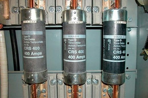
Current transformers used in metering equipment for 3-phase 400A electricity supply (photo credit: Wikipedia)
After the type of instrument has been defined that is most suitable for requirements, if the measurement is conducted through indirect insertion, the accessories of the measuring system such as current and voltage transformers must be chosen carefully.
If an 800 A current has to be measured, in most cases the instrument cannot be connected directly to the line. A current transformer that is suitable for the application must therefore be selected. The chosen parameters of a current transformer are not only rated current, secondary current and power but also the type of assembly. Flexible and stiff cables or bars for carrying power can be installed in a power panel.
The transformers can be of different types, depending on the assembly system: a through cable or a cable with a wound primary, transformers for assembly on horizontal or vertical bars.
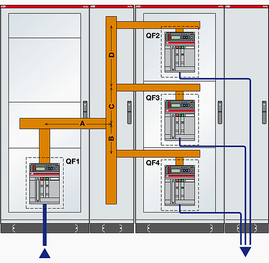
4. Cabling and wiring diagrams
Connecting analogue instruments is very simple; it in fact suffices to connect the phase and neutral cables to the instrument’s.terminal. Two cables fo the auxiliary supply must always be connected for digital instruments.
Power meter series 800 – wire connection with 3 CTs and no PT
Multifunction instruments can be used in different distribution systems.
In three-phase systems with distributed neutral three current transformers are required. In three-phase systems without distibuted neutral in which the loads are balanced and symmetrical, an aron insertion can be carried out, i.e. two current transformers rather than three can be used; the instrument will calculate by difference the third phase that is not measured directly, considering it to be the same as the other two.
In multifunction instruments not only the cables connected to the measurement, but also the RS485 serial port and the analogue and digital outputs and inputs have to be cabled.
5. Protecting the instrument and earthing
In order to ensure that the instrument is properly protected, fuses must always be fitted to the supply cables of digital instruments and to the voltmeter measuring inputs.
Earthing the secondaries of the CTs ensures an earth connection if the transformer develops a fault and does not affect the measurement. If there is a great potential difference between neutral and earth, this could affect the measurement negatively, in the case of instruments with measuring inputs that are not galvanically insulated.
6. Setting digital instruments
Before digital instruments start operating they must be set with the parameters of the measuring system and the communication parameters. The main measuring parameters are the transformation ratios of the CTs and of the VTs, which are defined as the mathematical ratio between the nominal value and the value of the secondary;
For example, setting the transformation ratio of an CT CT3/100 with a secondary at 5 A means setting kCT = 100: 5 = 20
7. Troubleshooting during final testing
The main problems that arise during the test phase may be due to incorrect installation of the instruments and the accessories. Always check that the wiring complies with the instruction manual.
Errors during installation
The following errors are those that are most frequently committed when installing a measuring instrument:
Inverting the secondaries of the CTs
Inverting the phases of the current and voltage measuring inputs
Failure to eliminate the short circuit of the secondaries of the CTs
Setting an incorrect transformer ratio.
Reference: Practical guide to electrical measurements in low voltage switchboards – ABB (Download)
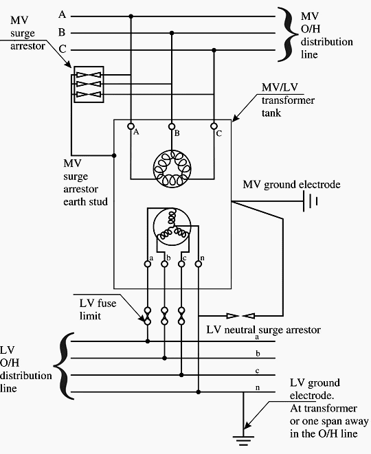
To maintain the LV neutral potential to as close to earth potential as possible thereby prospective touch voltages in all the grounded metal parts of equipment
To provide a low-impedance return path for any LV ground faults
To ensure operation of MV protection in the event of an inter-winding fault (MV and LV) within the transformer.
The surge arrestors of MV lines are connected to the transformer tank, which in turn is grounded through the MV, ground electrode. This limits the voltage between the tank and the lines to the voltage drop across the arrestors in the event of a surge.
In case the arrestors are connected by a separate lead to the ground, the voltage drop across the resistor would also additionally appear between lines and tank and cause insulation failure.
Though it is theoretically possible to have a combined ground at the transformer for both MV and LV, such a practice may lead to unsafe conditions in the event of an MV to LV fault. Figure 1 shows the reason.
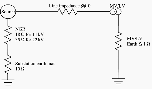
Figure 1 – Equivalent circuit for combined MV/LV grounding
The total impedance for a fault between HV and MV winding (neglecting the line impedance and the leakage impedance of the transformer windings) is the substation ground mat resistance of 10 Ω, the NGR (neutral grounding resistance) value and the MV/LV combined ground electrode resistance assumed as 1 Ω.
For a 22 kV system (with line to ground voltage of 12 700 V) the current flow is:
IG = 12 700 / (10 + 35 + 1)
Where 35 Ω being the NGR (neutral grounding resistance) value for a 22 kV system.
This gives a figure of 276 A. This current will cause the potential of 276 V to appear on the transformer tank and through the neutral lead to the enclosures of all equipment connected in the LV system with respect to true earth potential (this is because in TN-C-S type of systems, which we saw in the last chapter, the neutral and equipment ground are one and the same).
This value is unacceptably high. In actual practice, the line and transformer impedances come into play and the value will therefore get restricted to safe values. Use of combined MV and LV grounding is therefore possible only if the ground resistance can be maintained below 1 Ω.
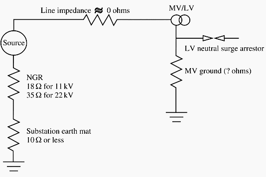
In view of the difficulty of maintaining a very low combined ground resistance arrived at above, the code allows the use of a separate ground for the LV neutral away from the transformer. The only point of connection between the LV system and the transformer tank is the LV neutral surge arrestor whose grounding lead is connected to the transformer tank (refer Figure 2 below).
Figure 2 – Equivalent circuit for separate MV ground
The problem with this connection is that a fault within the transformer (MV winding to core fault) resulting in rise of voltage can cause a high enough voltage to ground causing the neutral surge arrestor to fail and communicate the high voltage into the LV system.
Assuming a maximum LV voltage of 5000 V for withstand of neural surge arrestors, the voltage rise across the MV ground electrode resistance should not be greater than this value.
For a 22 kV system (with line to ground voltage of 12 700 V) the ground electrode voltage can be calculated using the potential division principle as follows:
5000 / 12 700 = Rm / (Rm + 10 + 35)
where Rm is the resistance of MV ground electrode. It can be calculated that Rm can have a value of 29 Ωto be able to limit the voltage.
For 11 kV system, a value of 100 Ωis permissible. The limit for the electrode resistance should also consider the ground fault current so that the MV ground fault relay can operate reliably to isolate the fault. A value of 30 Ωis taken as the limit for ground electrode systems for all MV systems. Standard configurations are available in the code for 30 Ω electrodes and can be used in the design.
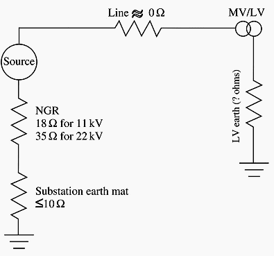
The LV electrode resistance should be normally expected to permit sufficient fault currents for detection. Since with the LV line to neutral voltage of 240 V, the resistance limit works out to 2.4 Ωif a ground fault current of 100 A is to be obtained.
However, with the TN-C-S type of system, all equipment enclosures are directly connected to the neutral at the service inlet itself and thus the current flow does not involve the ground path at all.
So, the limit of LV grounding resistance is decided by the criteria of obtaining sufficient fault current when there is an MV to LV fault without involving the tank or core (refer Figure 3).
Figure 3 – Equivalent circuit for separate LV ground
Assuming an MV earth fault protection setting of 40 A, the ground loop resistance can be arrived at 318 Ω (12 700/40) for 22 kV system. The permissible ground electrode resistance works out to 273 Ω (after taking off the values of NGR (neutral grounding resistance) and substation ground resistance).
If we consider a safety factor of 400%, the maximum value of LV ground resistance can be taken as 68 Ω. The safety factor will ensure that the seasonal changes of soil resistivity will have no adverse effect on protection operation. Standard configurations are available in the code for 70 Ω electrodes and can be used in the design.
For “protection against electric shock under fault conditions“ in TN systems, overcurrent and residual current devices have been approved.
For the use of surge protective devices (SPDs) this means that these protective devices may only be arranged downstream of the devices for “protection against electric shock under fault conditions” in order to ensure that the measure to protect against life hazards also operates in the event of a failure of an SPD (surge protective device).
If a Type 1 or 2 surge protective device (SPD) is installed downstream of a residual current device, it has to be expected that, because of the discharged impulse current to PE, this process will be interpreted as residual current by a residual current device (RCD), and it interrupts the circuit.
Equivalents for SPD classifications
(In the following lines we will use the designation SPD Type 1,SPD Type 2, SPD Type 3)
Definition acc. to IEC 61643
Definition acc. to EN 61643
SPDs which withstand the partial lightning current with a typical waveform 10/350 μs require a corresponding impulse test current Iimp The suitable test current Iimp is defined in the Class I test procedure of IEC 61643-1
SPD class I
SPD Type 1
SPDs which withstand induced surge currents with a typical waveform 8/20 μs require a corresponding impulse test current In The suitable test current In is defined in the Class II test procedure of IEC 61643-1
SPD class II
SPD Type 2
SPDs that withstand induced surge currents with a typical waveform 8/20 μs and require a corresponding impulse test current Isc The suitable combination wave test is defined in the Class III test procedure of IEC 61643-1
SPD class III
SPD Type 3
Moreover, if an SPD Type 1 is loaded with partial lightning currents it must be assumed that the high dynamics of the lightning current will cause mechanical damage on the residual current device (Figure 1 below).
This would override the protective measure “protection against electric shock under fault conditions”.
Figure 1 – RCD destroyed by lightning impulse current
Of course, this must be avoided. Therefore both lightning current arresters Type 1 and SPDs Type 2 should be used upstream of the residual current device. Hence, for SPDs Type 1 and 2, the only possible measure for “protection against electric shock under fault conditions” is using overcurrent protective devices.
The use of SPDs must therefore always be considered in conjunction with a fuse as the overcurrent protective device. Whether or not a supplementary separate backup fuse must be designated for the arrester branch, depends on the size of the next upstream supply fuse and the backup fuse approved for the SPD.
The following maximum continuous voltages apply to SPDs Type 1, 2 and 3 when used in TN systems (Figures 2 and 3 A to B):
Figure 2 – “3-0” circuit in TN-C systems Figure 3A – “4-0” circuit in TN-S systems Figure 3B – “3+1” circuit in TN-S systems
TN-C-S systems
Figure 4 illustrates an example of the connections for use of lightning current arresters and surge protective devices in TN-C-S systems.
Figure 4 – Use of SPDs in TN-C-S systems
It can be seen that SPDs Type 3 are used downstream of the residual current device (RCD). In this context, please note the following:
As a result of the frequency of switching surges in the terminal circuits, SPDs Type 3 are primarily employed to protect against differential mode voltages. These surges generally arise between L and N.
A surge limitation between L and N means that no impulse current is discharged to PE. Thus, this process can also not be interpreted as residual current by the RCD. In all other cases, SPDs Type 3 are designed for a nominal discharge capacity of 1.5 kA. These values are sufficient in the sense that upstream protective stages of SPDs Type 1 and 2 take over the discharge of high energy impulses. When using an RCD capable of withstanding impulse currents, these impulse currents are not able to trip the RCD or cause mechanical damage.
TN-S systems
The Figures 5 to 9 illustrate the use of SPDs as part of the lightning protection zones concept, and the required lightning and surge protective measures for a TN-C-S system.
Use of SPDs in TN-S systems // Example
Figure 5 – Use of SPDs in TN-S systems
SPDs used in TN systems // Examples
Example 1 // Office Building – Separation of the PEN in the main distribution board
Figure 6 – SPDs used in TN systems – Example: Office Building – Separation of the PEN in the main distribution board
Example 2 // Office Building – Separation of the PEN in the subdistribution board
Example: Office Building – Separation of the PEN in the subdistribution board
Example 3 // Industry – Separation of the PEN in the subdistribution board
Figure 8 – SPDs used in TN systems – Example: Industry – Separation of the PEN in the subdistribution board
Example 4 // Residential building
Figure 9 – SPDs used in TN systems – Example: Residential building
The purpose of auxiliary power supply systems is to cater for the necessary energy for the operation of primary and secondary devices at the substation. The auxiliary power systems are normally divided in two categories, namely the AC system and the DC system(s).
The AC system normally operates with the country’s standardized utility low voltage level, for example 400 V 50 Hz. The DC systems are already described in one of the previous technical articles, so they won’t be mentioned here.
The loads fed by the AC auxiliary supply system are normally so called inessential loads, which are not crucial for the substation operation.
These loads would typically include the following:
Substation building(s) climate control and lighting
Outdoor equipment and indoor panels desiccation heaters
Usually the AC-power distribution at a substation utilizes the same voltage levels and principles as the normal household electrification of that country. Depending on the practice and the legislation in the target country, the AC distribution system can either be 4-wire (TN-C) or 5- wire (TN-S).
Elements of AC Auxiliary System
The main components of AC auxiliary supply system are:
Station auxiliary transformer(s),
AC main distribution switchgear,
AC sub-distribution board(s) and
The cable network
As with the DC auxiliary system, the AC auxiliary system can be also doubled. The doubled system would utilize two station auxiliary transformers, each supplying their own section in the main distribution switchgear. The doubled system can be also constructed so that the second supply is coming from an external source, often the surrounding aerial low voltage network.
The supply for the station auxiliary transformer is arranged from the medium-voltage level side. If there is no medium voltage available at the substation, like a 330/132 kV substation, normally the main power transformer’s tertiary (stabilizing) winding is utilized.
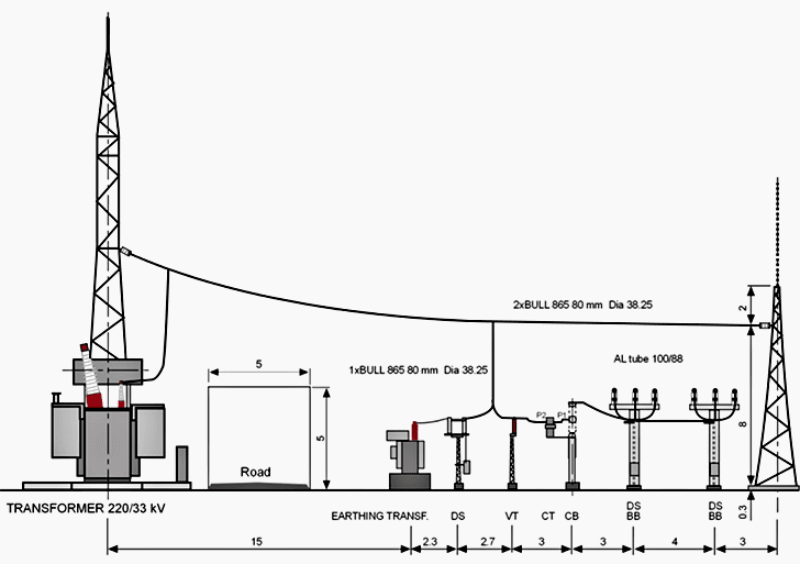
The following figure shows an application where the combined station auxiliary and system- earthing transformer is supplied directly from a main power transformer’s (220/33 kV) low- voltage side.
Figure 1 – Combined station auxiliary and system earthing transformer connected directly to 33 kV
Figure 1 shows the auxiliary transformer’s physical placement as a part of the bay layout. Since the 33 kV side of a 220/33 kV power transformer is delta-connected, thus not offering a point for system earthing, the station auxiliary transformer is also serving as a system-earthing connection point.
The station auxiliary transformer has a connection group of ZNyn. The zigzag-connected primary winding provides the 33 kV system earthing point. By its nature, the zigzag connection provides also means to limit the earth fault currents into desired level.
The zero-sequence impedance of a zigzag winding can be influenced, within certain limits, by the transformer design.
Figure 2 – Station auxiliary and system earthing transformer as a part of the bay layout
When the ZNyn-connected earthing transformer is used for low voltage AC-power supply, the magnitude of the available earth fault current on the low voltage side has to be checked, since the zero-sequence reactance of the transformer can limit the current to an unacceptably low value.
The primary AC auxiliary system typically uses effectively direct grounded system, having all the supply points connected to earth. Affected by the legislation in each country, the system is either utilizing the 4-wire or 5-wire principle.
The use of a 5-wire (TN-S) system enables also the use of residual current protection in the whole system or in selected feeders.
The residual-current protection measures the sum current in all of the phases and the neutral. The sum current must be zero during normal operation. During a system insulation fault, the sum current will rise and the residual current protection switch will open, separating (de-energizing) the section behind the measurement point from the rest of the system.
A typical operating current for residual switch is either 30mA or 300mA, the first being used for human protection and the latter for fire protection.
Figure 3 – Principle of TN-S system with double supply
Reference // ABB’s Distribution Automation Handbook – Elements of power distribution systems
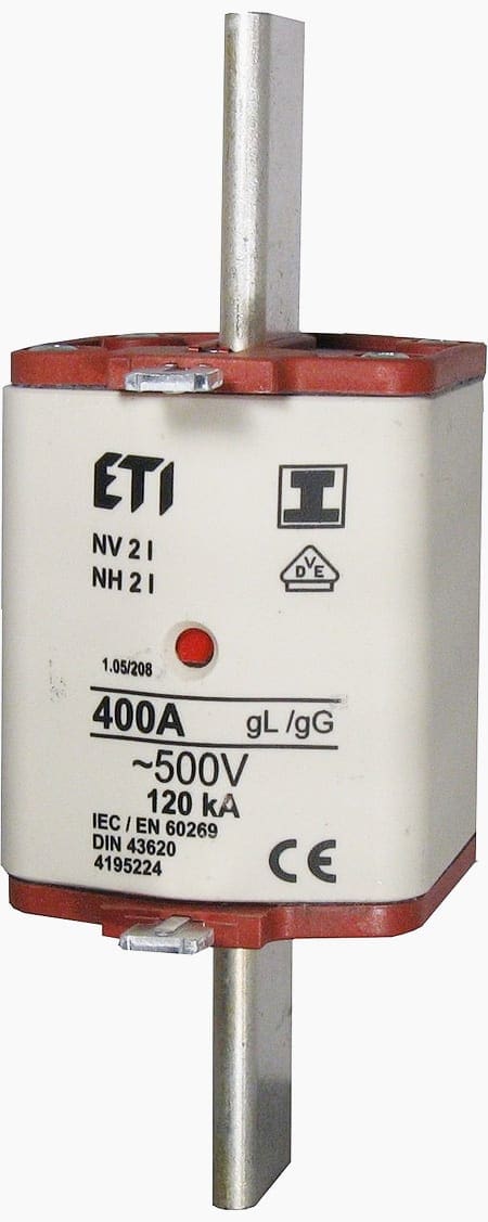
The simplest of all overcurrent protective devices are fuses. A fuse is an overcurrent protective device with a circuit-opening fusible part that is heated and severed by the passage of the overcurrent through it.
Let’s talk about ten important definitions that are of interest for low voltage fuses //
The RMS current that the fuse can carry continuously without deterioration and without exceeding temperature rise limits. In accordance with NEC article 210.20 a fuse (or any branch-circuit overcurrent device) should not be loaded continuously to over 80% of its ampere rating unless the assembly, including the fuse and enclosure, is listed for operation at 100% of its rating.
A current-limiting fuse interrupts all available currents its threshold current and below its maximum interrupting rating.
A current-limiting fuse limits the clearing time at rated voltage to an interval equal to or less than the first major or symmetrical loop duration. It limits peak let-through current to a value less than the peak current that would be possible with the fuse replaced by a solid conductor of the same impedance.
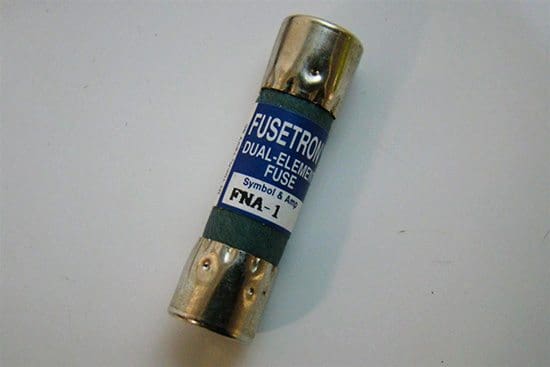
A cartridge fuse having two or more current-responsive elements in series in a single cartridge. The dual-element design is a construction technique frequently used to obtain a desired time-delay response characteristic.
A measure of heat energy developed within a circuit during the fuse’s melting or arcing. The sum of melting and arcing I2t is generally stated as total clearing I2t.
For Class H, K, J, and R fuses, a minimum opening time of 10s to an overload current five times the ampere rating of the fuse, except for Class H, K, and R fuses rated 0-30 A, 250 V, in which case the opening time can be reduced to 8s.
For Class G, Class CC, and plug fuses, a minimum time delay of 12s on an overload of twice the fuses’ ampere rating.
Time delay low voltage fuses (photo credit: ife-p.org)
The RMS voltage at which the fuse is designed to operate. All low voltage fuses will operate at any lower voltage (note that this is characterized as AC or DC, or both).
Low voltage fuses are classified according to the standard to which they are designed. The 1 table lists the various fuse classes and pertinent data for each class.
Fuses, like most protective devices, exhibit inverse time-current characteristics. A typical fuse time-current characteristic is shown in Figure 1.
Figure 1 – Typical class J fuse time-current characteristic
Logarithmic scales are used for both the time and current axes, in order to cover a wide range.
The characteristic represents a band of operating times for which the lower boundary is the minimum melting time curve, above which the low voltage fuses can be damaged. The upper boundary is the total clearing time curve, above which the fuse will open. For a given fault current, the actual fuse opening time will be within this band.
Table 1 – Low Voltage fuse classes //
Table 1 – Low Voltage fuse classes
In some cases the fuse average melting time only is given. This can be treated as the fuse opening time with a tolerance of ±15%. The -15% boundary is the minimum melting time and the +15% boundary is the total clearing time. Note that the time-current characteristic does not extend below 0.01 seconds. This is due to the fact that below 0.01 seconds the fuse is operating in its current-limiting region and the fuse I2t is of increasing importance.
The time-current characteristic curves are used to demonstrate the coordination between protective devices in series. The basic principle of system protection is that for a given fault current ideally only the device nearest the fault opens, minimizing the effect of the fault on the rest of the system.
This principle is known as selective coordination and can be analyzed with the use of the device time-current characteristic curves.
As an example, consider a 480 V system with two sets of low voltage fuses in series, with a system available fault current of 30,000 A. Bus “A” is protected using 400 A class J fuses which supply, among others, bus “B.” Bus “B” is protected using 100 A class J fuses. Coordination between the 400 A and 100 A fuses can is shown via the time-current curves of figure 2, along with a one-line diagram of the part of the system under consideration.
Because the time bands for the two fuses do not overlap, these are coordinated for all operating times above 0.01 seconds.
It can also be stated that these two sets of fuses are coordinated through approximately 4200 A, since at 4200 A Fuse A has the potential to begin operating in its current-limiting region. Fuse B has the potential to begin operating its current-limiting region at 1100 A. For currents above approximately 4000 A, therefore, both sets of fuses have the potential to be operating in the current-limiting region.
When both sets of fuses are operating the current-limiting region the time-current curves cannot be used to the determine coordination between them.
Instead, for a given fault current the minimum melting I2t for Fuse A must be greater than the maximum clearing I2t for Fuse B. In practice, instead of publishing I2t data fuse manufacturers typically publish ratio tables showing the minimum ratios of fuses of a given type that will coordinate with each other.
Figure 2 – Fuse coordination example
Low voltage fuse AC interrupting ratings are based upon a maximum power factor of 0.2, corresponding to a maximum X/R ratio of 4.899. In order to evaluate a low voltage fuse’s interrupting rating on a system with a higher X/R ratio the system symmetrical fault current must be multiplied by a multiplying factor:
where:
The available symmetrical fault current multiplied by the multiplying factor (MULT) per formula above can be compared to the fuse interrupting rating.
The use of low voltage fuses requires a holder and a switching device in addition to the fuses themselves. Because they are single-phase devices, a single blown fuse from a three-phase set will cause a single-phasing condition, which can lead to motor damage.
Also, replacement low voltage fuses must be stocked to get a circuit with a blown fuse back on-line quickly. For these reasons, the use of low voltage fuses in modern power systems is generally discouraged. For circuit breakers that have a short-time rating.
Reference // System Protection – Bill Brown, P.E., Square D Engineering Services
A real danger can arise when the non-current-carrying metalwork of an installation is connected to the system’s neutral, as is the case with a TN-C-S-fed system. The ground system is effectively in parallel with the neutral and can thus share the normal neutral current under certain conditions.
This electric current will not only be that of the installation itself, but may also be part of the neutral current of neighboring installations. It therefore follows that the grounding wires of an installation may carry a significant current even when the main supply to that installation is switched off. This could clearly cause a hazard if in a potentially explosive part of an installation, such as a petrol storage tank, the ground wire were to carry part of the neutral current of a number of installations.
For this reason, the use of TN-C-S supply system is prohibited in the case of petrol-filling stations. Such installations must be fed from TN-S supply systems.
Schematic of a TN-C-S system
The difficulty of ensuring that bonding requirements are met on construction sites means that TN-C-S supplies must not be used for temporary supplies. Electricity Supply Regulations also do not permit the use of TN-C-S supplies to feed caravans and caravan sites.
Let’s discuss the requirements for these consumers briefly below //
The objective of electrical installation on a construction site is to provide lighting and power to enable the work to proceed. By the very nature of the installation, it will be subjected to the kind of rough treatment, which is unlikely to be applied to most fixed installations.
Those working on the site may sometimes be ankle deep in mud and thus are particularly susceptible to an electric shock. They may be using portable tools in situations where danger is more likely than in most factory situations.
Special regulations are applicable to construction power installations to minimize the danger to working personnel. Apart from the use of TN-S system certain additional requirements are also applicable.
These are as follows:
Requirement #1
Distribution and supply equipment must be protected to IP44. This means provision of mechanical protection from objects more than 1 mm thick and protection from splashing water. Such equipment will include switches and isolators to control circuits and to isolate the incoming supply.
The main isolator must be capable of being locked or otherwise secured in the ‘off’ position. Emergency switches should disconnect all live conductors including the neutral.
Temporary power supply switchboard for contruction site (photo credit: zpue.pl)
Requirement #2
Sockets on a construction site must be separated extra-low voltage (SELV) or protected by a residual current circuit breaker (RCD) with an operating current of not more than 30 mA, or must be electrically separate from the rest of the
supply, each socket being fed by its own individual transformer.
The SELV is unlikely for most applications because 12 V power tools would draw too much current to be practical. Most sockets are likely to be fed at 110 V from centertapped transformers and so will comply with this requirement.
Requirement #3
Cables and their connections must not be subjected to strain, and cables must not be run across roads or walkways without mechanical protection. Circuits supplying equipment must be fed from a distribution assembly including overcurrent protection, a local RCD if necessary and socket outlets where needed.
Socket outlets must be enclosed in distribution assemblies, fixed to the outside of the assembly enclosure or fixed to a vertical wall. Sockets must not be left unattached, as is often the case on construction sites.
Requirement #4
Such installations are also by their very nature temporary. As the construction proceeds they will be moved and altered. It is usual for such installations to be subjected to thorough inspection and testing at intervals, which will never exceed 3 months.
Requirement #5
The equipment used must be suitable for the particular supply to which it is connected, and for the duty it will meet on site. Where more than one voltage is in use, plugs and sockets must be non-interchangeable to prevent misconnection.
Six levels of voltage are recognized for a construction site installation. They are:
25-V single-phase SELV for portable hand-lamps in damp and confined situations
50-V single-phase, center-point grounded for hand lamps in damp and confined situations
400-V three-phase, for use with fixed or portable equipment with a load of more than 3750 W
230-V single-phase, for site buildings and fixed lighting
110-V three-phase, for portable equipment with a load up to 3750 W
110-V single-phase, fed from a transformer, often with a grounded center tapped secondary winding, to feed transportable tools and equipment, such as floodlighting, with a load of up to 2 kW. This supply ensures that the voltage to ground should never exceed 55 V. The primary winding of the transformer must be RCD protected unless the equipment fed is to be used indoors.
The requirements for construction sites will also apply to:
Sites where repairs, alterations or additions are carried out
Demolition of buildings
Public engineering works
Civil engineering operations, such as road building, coastal protection, etc.
The special requirements for construction sites do not apply to temporary buildings erected for the use of the construction workers, such as offices, toilets, cloakrooms, dormitories, canteens, meeting rooms, etc. These areas/buildings are not subject to changes as construction work progresses and are thus exempt from these requirements.
Another typical situation where TN-C-S systems are not used is the marina power supply system. A marina is a location, often a harbor, for leisure craft to berth.
Like residential caravans, such craft require external power supplies, and this section is intended to ensure the safety and standardization of such supplies. The marina will often include shore-based facilities such as offices, workshops, toilets, leisure accommodation, and so on and is exempt from these special requirements.
Marine power supply (photo credit: whitehallannapolis.com)
The electrical installation of a marina is subject to hazards not usually encountered elsewhere. These include the presence of water and salt, the movement of the craft, increased corrosion due to the presence of salt water and dissimilar metals and the possibility of equipment being submerged due to unusual wave activity in bad weather.
The neutral of a TN-C-S system must not be connected to the grounded system of a boat so that the hazards, which follow the loss of continuity in the supply PEN conductor, are avoided.
This rules out the use of TN-C-S supplies for marinas. Where this is the supply provided, it must be converted to a TT system atthe main distribution board by provision of a separate ground electrode system of driven rods or buried mats with no overlap of resistance area with any ground associated with the TN-C-S supply.
Example of a heavily burned hot conductor in the receptacle. This is another fire hazard not uncommon in the marina environment (photo credit: qualitymarineservices.net)
If the marina is large enough, it may be that the supply company will provide a separate transformer and a TN-S system.
A common installation method is to provide a feed from the shore to a floating pontoon via a bridge or ramp, and then to equip the pontoon with socket outlets to feed the craft moored to it. Socket outlets may be single or three phase. Where multiple single-phase sockets are installed on the same pontoon, they must all be connected to the same phase of the supply unless fed through isolating transformers.
Socket outlets should be positioned as close as possible to the berth of the vessel they feed, with a minimum of one socket per berth, although up to six sockets may be provided in a single enclosure. Each socket outlet must be provided with a means of isolation which breaks all poles on TT systems and must be protected by an over-current device such as a fuse or a circuit breaker.
Groups of socket outlets must be RCD protected. Each socket orgroup of sockets must be provided with a durable and legible notice giving instructions for the electricity supply.
A caravan is a leisure accommodation vehicle, which reaches its site by being towed by a vehicle. A motor caravan is used for the same purpose, but has an engine, which allows it to be driven; the accommodation module on a motor caravan may sometimes be removed from the chassis.
Caravans will often contain a bath or a shower, and in these cases the special requirements for such installations will apply. Railway rolling stock is not included in the definition as a caravan.
All dangers associated with fixed electrical installations are also present in and around caravans. Added to these are the problems of moving the caravan, including connection and disconnection to and from the supply, often by unskilled people. Grounding is of prime importance because the dangers of shock are greater.
Caravan vehicle power supply (photo credit: withoutahitch.com.au)
For example, the loss of the main protective conductor and a fault to the metalwork in the caravan is likely to go unnoticed until someone makes contact with the caravan whilst standing outside it.
The requirements of the Electricity Supply Regulations do not allow the supply neutral to be connected to any metalwork in a caravan, which means that TN-C-S supplies must not be used to supply them.
The power supply to a caravan must be made using approved type of coupler at a height of not more than 1.8 m from ground. The coupler socket (fixed to the caravan body) must have a spring-loaded lid, which will protect the socket when caravan is traveling.
A clear notice must be affixed near the socket to indicate voltage, current and frequency of the supply required by the caravan.
This socket must be connected to a main isolator with RCD protection with an operating current of 30 mA, which on operation will disconnect all live conductors. All metal parts of the caravan, with the exception of metal sheets forming part of the structure, must be bonded together and to a circuit-protective conductor, which must not be smaller than 4 mm2 except where it forms part of a sheathed cable or is enclosed in conduit.
There are locations such as swimming pools, saunas, hospitals, etc., where danger to human beings is more probable. The reason for this is that in some of the locations, the human beings are partly unclothed, without shoes and are in contact with water or their body is wet.
Swimming pool wiring (photo credit: mikeholt.com)
The effect of any contact with live electrical parts could therefore be particularly dangerous. A hospital where open-heart surgery is performed poses even greater danger because of the effect of stray electric currents finding their way to the human heart through medical appliances used in the treatment. Also explosive hazards may exist in certain hospital locations handling anesthetic gases.
The use of electrical systems in these cases will depend on the zone of use. These zones are defined in each case depending on the presence of vulnerable human body in the vicinity. Use of lower-voltage isolated systems, ground fault alarms and RCD is advised depending on the application.
Zone
Minimum degree of protection
A
IPX8
B
IPX5 IPX4 where water jets are not likely to be used for cleaning
C
IPX2 for indoor pools IPX4 for outdoor pools IPX5 where water jets are likely to be used for cleaning
The zonal concept for a particular swimming pool (credit: iee.org)
Without going into the details of the management modalities of the electric distribution or of the layout that an electrical system on board may have, it is possible to describe it in short, however giving the possibility to understand its structure and complexity.
In the power plants on board of big ships, or however in the most modern ships, such as for example line cruisers, the generation of electric energy occurs in the power station on board, which, in some cases, can be divided into two parts, one placed astern and the other at the bow.
Medium voltage distribution (see Figure 1 below) starts from the main switchboard which consists of two sections, each of them connected to one gen-set.
These bars are usually connected through a bus-tie which allows the power to be handled according to the specific needs, always with the point of view of keeping, even if reduced, such an efficiency that a good degree of safety and stability is ensured for the ship.
Figure 1 – General representation of the modalities of generation and MV supply
The medium voltage main busbar system or some distribution sub-switchboards deliver power, directly or through control devices (e.g. electronic converters) to:
Essential high power loads (e.g. the propellers or the thrusters for transverse motion);
Big power motors, for example for air-conditioning or for the typical functions linked to particular vessel typology;
Various substations in the service areas intended to supply LV power to all the power loads, small power loads or lights provided for that area.
Therefore, the secondary power supply of the LV switchboards starts from the substations, through MV/ LV transformers. These switchboards often offer the possibility of having redundant supply coming from other MV switchboards supplied in turn by the other half-busbar of the main MV switchboard.
From the LV switchboards a complex distribution network (see Figure 2) is originated and it supplies the different types of LV loads on board, such as the rudder, the winches or the essential auxiliaries of the motor and, moreover, the lightning plant, the entertaining, comfort and performance facilities, as well as the accommodation structures with kitchens and laundries.
The power plant must always guarantee service continuity; therefore, switchboards with two incoming feeders de- riving from other separate switchboards are provided.
In case of fault, putting out of service, as fast as possible, only the load involved or the section affected by the breakdown is important, thus realizing high selectivity for all the loads.
Figure 2 – General power substation diagram relevant to MV and LV distribution on board
In the previous paragraph, the MV generation voltage values have already been mentioned. Instead, as regards the distribution levels of the LV plant, till some years ago the standard value was 440V.
Due to the continuous increases of the tonnage and consequently of the power required on board, for the dificulty in handling the higher and higher rated currents and the short-circuit current values, the voltage supply has been changed and passed to 690V and in some rare and particular cases to 1000V.
This has implied some advantages, such as:
Partial reduction of the fault current values,
Reduction of the cross sectional areas of the cables and consequently of weights and overall dimensions,
Reduction of voltage drops and bigger admissible lengths of cables and an increase in the power of the motors which can be directly connected to the primary network and generally of all the loads of the Main Switchboard.
Low voltage final distribution is carried out at lower voltages (400V/230V), obtained through LV/LV transformers. The frequencies most commonly used are 50Hz or 60Hz according to different aspects, such as for example the type of naval construction and the country of origin.
For special loads, or more simply in the military eld, dedicated circuits are required in the presence of 400Hz.
Typically, the direct current has voltage values of 48V, 110V or 125V are maintained for those particular circuits, for example, where devices for battery recharging or for automation auxiliary circuits are provided.
Redundant supply //
As already said, also the lack of supply for the fundamental utilities must be avoided for safety on board. Therefore the distribution system shall provide for the possibility of a redundant supply.
This can be obtained usually through an open ring system.
For example dividing the MV main busbar, which closes if needed, so that the power supply to the electric propulsion engines is ensured in order not to jeopardize the ship maneuver-ability, or for LV switchboards to provide the possibility of a double supply deriving from other switchboards, or also through adequate designing of the emergency power station.
Electrical power plants on board are typically in alternating current since they result to guarantee a better management in terms of costs and reliability in comparison with direct current ones.
Will be continued soon…
Reference // Generalities on naval systems and installations on board – ABB
The MV primary distribution network generally consists in a three-phase system with three conductors without neutral. Such system is usually managed with the neutral of the star point isolated from earth or connected with earth through a resistance or a Petersen coil, thus allowing a reduction in the values of leakage and short-circuit currents. In this way, a first fault with insulation loss does not represent a hazard and allows the system to be maintained in service without the intervention of the protection.
Obviously the fault must be signaled and standard service conditions must be immediately restored so that it can be avoided that the first fault turns into a double fault to earth, which is extremely dangerous in IT systems.
Once, when onboard installations were not very wide and the powers involved quite small, the secondary distribution system consisted in a single-phase network with two insulated conductors or three conductors with the medium point of the transformer connected to earth.
Nowadays, since the powers involved have remarkably increased, it is preferred to use a four-wire three-phase system, that is with distributed neutral and in the most cases not connected with earth, with the possibility of disposing easily of the line-to-line and of the phase voltages.
Generally, the secondary distribution network is radially distributed with the possibility of double switchboard supply through two different lines, thus realizing the reserve connection to the load. The choice of using one type or the other depends on the plant conditions and it is carried out either by means of a switch or of interlocked circuit-breakers.
MV main distribution networks have a different structure according to the type of ship and to the installed power. They can be of simple radial type with substations or sub-switchboards.
The simple radial diagram (see Figure 1) includes a main switchboard with a single busbar, from which the output feeders for all the LV power consumers start. This con guration results to be particularly critical since a fault on the main switchboard may jeopardize the reliability of the services on board.
Figure 1 – Diagram of principle for radial distribution
The compound radial diagram (see Figure 2) is fitter than the previous one for the realization of medium power plants and comprises a main switchboard with one or more main busbars and some sub-switchboards, which provide solely for the power supply delivery from the main switchboard to the distribution switchboards differently placed.
With this configuration there is a remarkable reduction in the number of the circuits derived from the main switchboard and therefore of the devices installed in the switchboard.
Figure 2 – Diagram of principle for compound radial distribution
Instead, as regards the service continuity of the users derived from different distribution sub-switchboards, a remarkable importance is represented by the correct sizing of the chain of circuit-breakers positioned at the different levels of the distribution system so that it is possible to obtain the tripping of the circuit-breaker affected by the fault only, thus guaranteeing power supply for the other loads and sub-switchboards.
To ensure power supply continuity, the radial system is often structured with a reserve ring (Figure 3) intended for the supply of the substations having the main line interrupted, or even the whole substation group in case of a serious fault on the semi-busbar of the main switch- board usually supplying them.
In this case, which is to be considered very heavy and hard, only half the generators results to be available and consequently half the energy power installed. The ring shall be sized to provide for the needs of the plant foreseen for this operation situation, which, as it is evident, is of extreme emergency.
Figure 3 – Diagram of principle for distribution with ring circuit
The plant on board may be divided into three main parts, represented by:
1. Main plant
The main plant, consisting of the essential services of the ship, such as the propulsion or the circuits intended for priority functions on board, each of them characteristic of the ship typology (e.g. the circuits intended for gas pumping or compression for a gas carrier, or the circuits intend for the control of the devices for load handling on shipping containers).
2. Auxiliary circuits //
The auxiliary circuits which include power production and distribution systems for lightening and auxiliary motive force;
3. Special installations //
The special installations for which a particular technology has been developed:
Telephone installations,
Electronics devices for different uses,
Telegraphs,
Torquemeters,
Integrated navigation systems,
Fire warning devices.
Another main difference concerns the distinction which can be made between essential and non-essential loads, which influence the distribution system which supplies them.
The first ones are those for which supply and proper operation are to be guaranteed also under emergency conditions, since they carry out functions indispensable to the safety of the vessel. Among them, first of all the propulsion system, the control systems of motors, helms and stabilizer paddles, the re-prevention systems, the alarms, the communication and auxiliary systems for navigation, the emergency lightening.
Also those loads which contribute to create the best comfort or a better safety for passengers’ life on board, such as the air-conditioning or water-aspiration system, are to be considered essential.
The electrical system, in compliance with the Naval Regisisters’ rules, provide also an emergency electrical station positioned in another area with respect to the power station on board, usually on one of the high decks and however over the waterline. The power station consists of an autonomous LV diesel-generator set (440V or 690V), in the order of some MW.
The diesel engine under consideration shall be able to start also when the main network cannot deliver energy and this is usually obtained by means of a connection to the UPS system. A set of capacitors is present to guarantee energy availability also during the starting time of the emergency generator. Under standard operating conditions, that is in the presence of voltage on the mains, a rectifier shall have the task of delivering to the capacitor banks the energy necessary to keep the maximum charge.
In case of malfunctioning of the main station, an automatic control sequence provides for switching to the emergency switchboard the power delivery of the part of the plant to which the priority loads, which must work also in emergency case, are connected (e.g. emergency lightning, re pumps, steering devices and auxiliary equipment indispensable for the machinery systems, communication and signaling networks and other circuits).
Besides, due to environmental constraints, in harbors ships must turn their diesel engines off thus interrupting electric generation. Then they must connect to the on-shore grid, normally to a LV source, or in the most modern solutions to a MV tap made available in the port.
This procedure, defined High-Voltage Shore Connection (HVSC) finds favor with the harbor management authorities worldwide, allows for a reduction in the polluting emissions of ships at berth, improving air quality in the port areas and in the surrounding ones.
HVSC technology (Figure 4) allows power supply directly from the wharf to the vessel to ensure operation of the machinery systems and installations on board (refrigerators, illumination, heating and air-conditioning) and allow the diesel engines normally used to supply electrical generators on board to be turned off.
This operation in parallel, which is necessary for onboard electrical power supply must not cause problems of power quality to the onshore distribution grid.
To give an idea of the environmental impact, a big line cruiser at berth for 10 hours, if using onshore power supply, avoids burning of up to 20 metric tons of fuel, which is equivalent to 60 metric tons of carbon dioxide not emitted into the atmosphere, which is the annual emission of 25 cars.
Shore-to-ship electric power solutionHigh-Voltage Shore Connection (photo credit: sam-electronics.de)
This technical article has the aim of helping the panel builder and the designer in the construction of ABB SACE ArTu low voltage switchboard. To this purpose, starting from the single-line diagram of a plant, it is possible to arrive – by selecting the suitable components – to the construction of an switchboard and to the relevant declaration of conformity with the Std. IEC 61439-2.
Characteristics of the low voltage switchboard, according to the specification:
“not separated” switchboard;
IP 65;
exposed wall-mounted.
Figure 1 – Single-line diagram of LV switchgear
Single-line diagram
Let us suppose that realization of a main distribution switchboard is required, to be placed immediately on the load side of a 2000kVA MV/LV transformer. Three 850A outgoing feeders from this switchboard supply other distribution switchboard, but they are not dealt with.
Due to reasons of selectivity with other circuit breakers of switchboards on the load side, air circuit breakers have been chosen branched from the busbars. The main distribution busbar short-circuit current is 48 kA.
Selection of the circuit breakers and of the conductors external to the switchboard
Circuit breakers //
As shown in the single-line diagram, the circuit breakers chosen are:
1 pc. of Emax E3N3200 PR121/P-LSI In 3200 (main circuit breaker of the switchboard QF1);
3 pcs. of Emax E1N1250 PR121/P-LSI In 1250 (circuit breakers for the three outgoing feeders QF2, QF3, QF4).
Conductors //
Incoming, from the transformer:
– 1 bus duct with Iz = 3150 A; L = 5 m
Outgoing from the switchboard, hypothesizing overhead installation on perforated trays, there are three low voltage cables:
– 1 cable L = 20m 3 x (3 x 120) Iz = 876,3 A;
– 1 cable L = 70m 3 x (3 x 120) Iz = 876,3 A;
– 1 cable L = 100m 3 x (3 x 120) Iz = 876,3 A.
Switchboard front, distribution system and metalwork structure
With regard to the positioning of the equipment, it has been decided to locate the main circuit breaker in one column, and the three outgoing feeders in another one. Since the power supply comes from below, it has been decided to position the circuit breaker QF1 at the bottom.
The switchboard assembly is of “not-separated” type. A possible layout of the busbars and of the circuit breakers is shown in the following figure:
Figure 2 – LV switchgear construction and devices
Distribution system //
As regards the busbars inside the switchboard, by first approximation, they are selected according to the size of the circuit breaker:
To get an Icw value suitable to the short-circuit current of the plant:
– 5 busbar holders PB3201 at a maximum distance of 425mm (Icw=50 kA) must be positioned.
Busbar holder 3200A – PB3201
Being in the presence of non-current limiting air circuit breakers, the Icw value of the distribution system shall be higher than the prospective Icp at the busbars.
Branch busbars of the circuit breakers
Circuit breakers QF2, QF3, QF4
(From the “Distribution Switchgear – General catalogue”)
BA1250 In= 1250 A (IP65) Icw max = 75 kA
1250A busbar
To get an Icw value suitable to the short-circuit current of the plant:
– 5 busbar holders PB1601 at a maximum distance of 425mm (Icw=50 kA) must be positioned.
Busbar holder PB1601, max. 1600A
Joining pieces between circuit breakers and busbars
(circuit breakers QF2, QF3, QF4)
Table 11.2 of clause 11.4 of the Technical Application Paper shows the cross-sectional areas of the busbars for the connection of the circuit breakers:
E3N323200 – A cross-sectional area 3 x (100 x 10)
E1N121250 – A cross-sectional area 1 x (80 x 10)
Table 11.2 of clause 11.4 of the Technical Application Paper: Cross-sectional areas of the busbars for the connection of the circuit breakers
Moreover, according to the terminal types, the maximum anchoring distance of the first anchor plate, shown at clause11.3 of the Technical Application Paper, shall be respected.
Clause 11.3 – Emax air circuit breakers an example of the maximum distance in mm (D) at which the first. Anchor plate of the busbars connecting to the circuitbreaker shall be positioned according to the type of terminal and making reference to the highest admissible value of short-circuit current and of its relevant peak.
Joints for busbars //
As indicated in the “Distribution switchgear. General catalogue” the following joints are necessary:
Joint from 3200 busbar to 3200 busbar, T joint, AD1073
Joint from 3200 busbar to 1250 busbar, AD1078
Busbar connection joints
Earthing busbar //
As shown on page 44 and 45 of this technical Application Paper, the earthing busbar shall have a minimum cross-sectional area equal to 1⁄4 of the cross-section of the main busbars. Therefore a bar 50×10 has been chosen.
Minimum cross-section of the corresponding protective conductor
Metalwork structure
As regards the metalwork structure, an ArTu K series switchboard with door (IP 65) is used. In order to house the circuit breakers, the vertical busbar system and the outgoing cables the following is used:
2 columns for the circuit breakers;
2 cable containers, one for the busbar system and one for the outgoing cables.
to house Emax E1-E2-E3 circuit breakers a switchboard assembly with 800mm depth and 600mm width and one installation kit KE3215 are required.
Kits for installing Emax circuit breakers X1-E1-E2-E3-E4
The cable container has obviously 800mm depth and 300mm width. In the general catalogue for distribution switchgear the fixing crosspieces for busbars with shaped section can be found:
For the 3200 A horizontal busbars (BA2000) the selected type of installation is number 5, for which the correct choice is two components TV6221 and one TV8011;
For the 3200 A vertical busbars (BA2000) the selected type of installation is number 2, for which the correct choice is TV8101 component;
For the 1250 A horizontal busbars (BA1250) the selected type of installation is number 5, for which the correct choice is two components TV6221 and one TV8011.
Busbar horizontal at any height – TV6221 (24 DIN mod W=600mm), TV8011
As specified in the general catalogue for distribution switchgear, the metalwork structure shall be completed by the side-by-side kits (AD1014).
Completed by the side-by-side kits (AD1014)
References //
Guidelines to the construction of a low-voltage assembly complying with the Standards IEC 61439 Part 1 and Part 2 – ABB
Distribution switchgear General catalogue // ArTu K – ABB


 of LV circuit breakers due to the switching operations")

 Switchgears (on photo\" Eaton Cutler Hammer Magnum DS Switchgear Inspection, and Transformer Testing)")


")